
What Is Embedded C? Basics and Applications
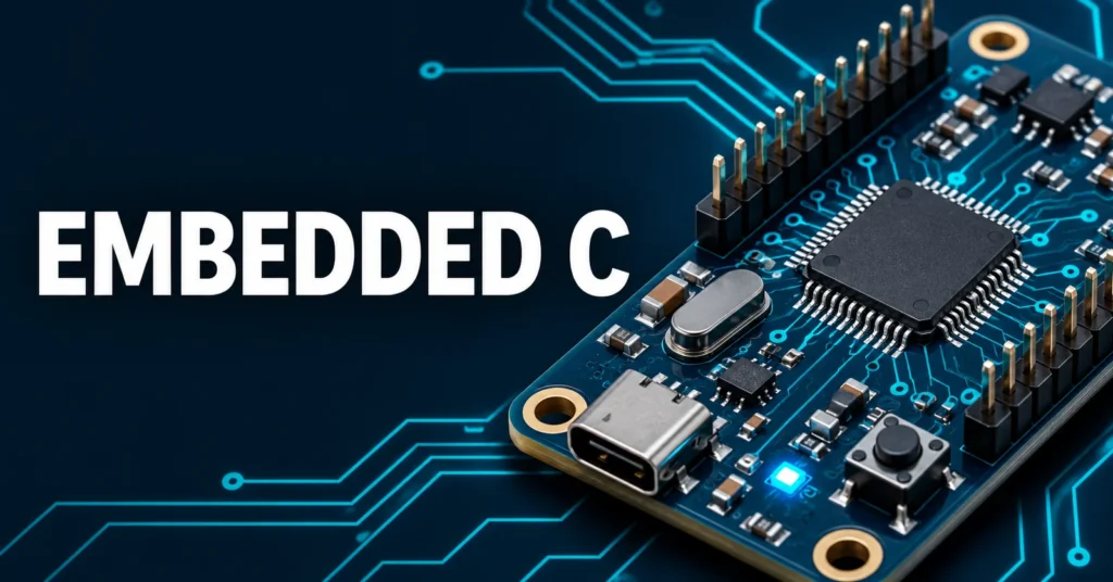
Press a button on a microwave and the display lights up. Somewhere inside, a small processor has read the button and decided what happens next.
Embedded C is the use of C to write software for dedicated devices, often microcontrollers. It lets you read sensors, control pins, respond to events, and decide what the device should do. If you’ve written C before, you’ll recognize the syntax. The hardware is what makes it feel different.
What is Embedded C?
Embedded C is C programming for a device that performs a dedicated job. The device might be a thermostat, a keyboard, or a controller inside a washing machine. The program it runs is called firmware. Firmware reads inputs, makes decisions, and drives outputs while working within the device’s limits on memory, power, and response time.
If you already know how to write a C function, use an array, or test a condition with if, those skills carry over. The new part is learning how your target exposes its hardware. A variable in ordinary application code might hold a menu selection. In firmware, reading a particular address can tell you whether a timer has expired.
Embedded C usually means standard C plus the headers, libraries, and compiler features your target needs. A device header might give a register a readable name. A toolchain might provide special syntax for declaring an interrupt handler. Check which parts belong to the language and which belong to the chip or compiler before you reuse code on another board.
Embedded C vs desktop C
The same C source can calculate an average or search a list on both a laptop and a microcontroller. The differences show up around that calculation. Who supplies the data? Who starts the program? Where does the result go? The answers shape the rest of your code.
| Aspect | Typical desktop C application | Typical microcontroller firmware |
|---|---|---|
| Startup | An operating system loads the program | Startup code runs after reset and calls main |
| Inputs and outputs | Operating system APIs handle files, displays, and devices | Peripheral drivers or registers handle pins, timers, and buses |
| Memory | Often has much more RAM and storage | Flash and RAM budgets may be tight |
| Timing | Often optimized for throughput or responsiveness | May have to meet a defined deadline for each event |
| Debugging | Debugger, terminal output, and application logs | Hardware debugger, serial output, or test equipment |
These are common setups. Some embedded products run Linux, and some microcontrollers run a real-time operating system. On a small bare-metal target, your code and its drivers handle the work directly. On an RTOS-based target, a scheduler can coordinate tasks, but you still have to budget their execution time and manage shared data.
How Embedded C talks to hardware
GPIO pins and registers
GPIO stands for general-purpose input/output. Configure a pin as an input and you can read a button. Configure it as an output and you can control an LED. Before either will work, you may need to enable the peripheral clock and choose the right pin function. Some pins can also serve as serial or timer signals.
A register is a small control or status location exposed by the hardware. On many microcontrollers, the CPU can reach peripheral registers through particular addresses. Individual bits may enable a feature, report an event, or select a mode. Device headers give these addresses and bit positions names so you can read the code without memorizing a list of numbers.
Bit masks, drivers, and volatile
A bit mask lets you work with selected bits inside a register. For example, 1u << 3 makes a mask for bit 3, counting from zero. For an ordinary read/write register, OR sets a bit, AND with an inverted mask clears it, and AND with the original mask tests it.
Read the register description before using those patterns. Some status bits clear when you write a one to them. A read-modify-write expression can accidentally clear several pending flags in such a register. Some devices also provide dedicated set and clear registers that avoid the need for a read-modify-write operation.
Hardware register definitions often use volatile to tell the compiler that accesses matter and that values may change outside the flow it can see. The qualifier alone cannot make a read-modify-write sequence atomic or keep an interrupt handler and main code from interfering with each other.
You can also use a vendor driver or a hardware abstraction layer. It can make the code easier to read and move between related chips. When an operation fails, the reference manual still helps you work out whether the clock, pin configuration, or peripheral state is responsible.
Polling, interrupts, and timers
With polling, your program checks an input or status flag repeatedly. That can be enough for an LED and a button. If the same loop spends half a second waiting on something else, though, a quick press could start and finish between checks.
An interrupt lets a peripheral request attention when an event occurs. The processor runs an interrupt service routine, then resumes its earlier work. A handler often records the event or copies a small piece of data and leaves longer processing for the main loop or a task.
Timers keep track of intervals using a hardware clock. For example, a timer clocked at 1 MHz after prescaling counts one million ticks per second. A 10 ms interval spans 10,000 ticks. Check how the timer counts before choosing its reload value. A counter that starts at zero and includes the reload value can need a setting of 9,999 for 10,000 ticks.
- Poll when the loop can check the input often enough.
- Use an interrupt when a short event needs timely attention or the processor can sleep between events.
- Use a timer when a job needs to run at a steady interval or after a known delay.
These methods often work together. An interrupt can report a button edge. A timer can give the contacts time to settle. The main loop can then read the pin and decide whether to count the press.
Your first Embedded C project
Start with an LED controlled by a push button. Many development boards have both built in, so you can test the code without wiring extra parts. Look up the board’s pin names and whether the button and LED are active high or active low. An active-low button reads as zero when pressed.
- Set up the target. Select the exact board or microcontroller in your toolchain and start with the board vendor’s example project.
- Configure the pins. Set the LED pin as an output and the button pin as an input. Enable a pull-up or pull-down if the circuit requires one.
- Read and respond. In the main loop, read the button state and set the LED accordingly. Start with the simplest behavior so you can verify each pin.
- Build and flash. Compile and link the firmware, then use the board’s programmer or bootloader to write it to flash memory.
- Test both states. Press and release the button. If the LED behaves backward, check the pin polarity and how your driver interprets the pin state.
Once that works, change the behavior so each press toggles the LED. That small change teaches you about edges and switch bounce. A held button stays pressed across many loop iterations, so compare the current and previous stable states and toggle only when the state changes to pressed.
Mechanical contacts can briefly open and close during one press. Sample the input on a timer and accept the change after several consistent readings. Try quick taps and longer holds. If you get double toggles, inspect the raw readings before changing the debounce interval.
Applications of Embedded C
Embedded C fits products that need close control of hardware and a clear idea of how much memory or time a task will use. The application determines what matters most. For a battery-powered sensor, the priority might be sleep current. For a motor controller, it might be how quickly the firmware responds to feedback.
- Cars. Firmware can read switches, communicate over a vehicle network, or control functions such as cabin lighting and window movement.
- Home appliances. A washing machine controller can read the door and water-level sensors, time each stage, and tell the motor driver when to run.
- Industrial equipment. Controllers can count encoder pulses, track motor speed, and report a fault to a supervisory system.
- Connected sensors. A battery-powered sensor can wake up, take a reading, transmit it, and return to sleep.
- Computer peripherals. Keyboard firmware scans a grid of switches, filters contact bounce, and reports key events to a host.
A thermostat illustrates how these pieces come together. Firmware reads a temperature sensor, compares the result with a setpoint, and controls an output. Two thresholds can help prevent rapid cycling. For example, a heating controller could turn on below 19.5 °C and turn off above 20.5 °C. The gap between those thresholds is called hysteresis.
Common Embedded C mistakes
Guessing about memory and timing
Use the linker’s memory report to check how much flash and RAM the program uses. Allow room for the stack, including interrupt handlers and nested function calls. A program can build successfully and still fail at runtime if it uses more stack than the target has available.
Use a logic analyzer or oscilloscope to measure timing when the result matters. A breakpoint stops the processor, which can change the behavior you’re investigating. Toggling a spare pin around a routine gives you a pulse whose width shows how long the routine took.
Mixing board setup with application logic
Keep pin setup and device access in small driver functions. Put decisions such as whether the heater should turn on in separate functions where you can pass in test values. That gives you a way to test thresholds and edge cases on your computer before you flash the board.
When something goes wrong, test one layer at a time. Confirm that the code reaches main, verify the input with a debugger or meter, then check whether the output pin changes. If a peripheral fails to respond, look at its clock and pin configuration before rewriting the application logic.

Comments
Comments are currently closed.