
Embedded Communication Protocols: UART, SPI, I2C and CAN
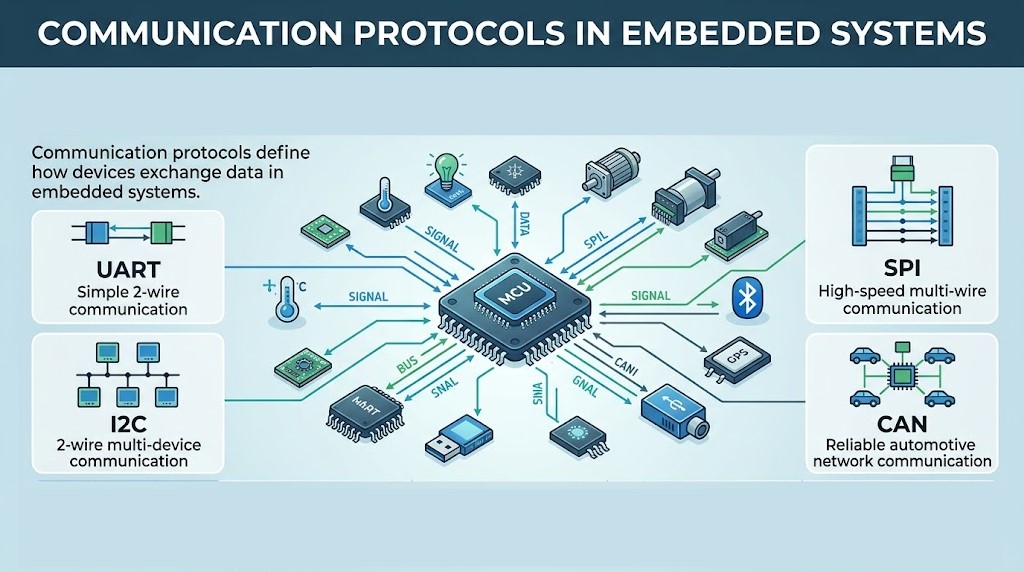
Two chips can use the same connector and still fail to understand each other. Matching the wires is only the beginning.
Embedded communication protocols define how devices exchange information, but electrical compatibility and timing matter just as much. UART, SPI, I2C, and CAN solve different connection problems. Choose one by the devices, distance, data rate, and reliability your project needs.
Embedded communication protocols at a glance
| Interface | Clocking | Typical connection | Important check |
|---|---|---|---|
| UART | No separate shared clock | TX and RX between devices | Baud rate, framing, logic levels |
| SPI | Controller supplies a clock | Clock, data lines, device select | Clock mode and device timing |
| I2C | Shared clock line | SDA and SCL bus | Addressing, pull-ups, capacitance |
| CAN | Bit timing synchronized on the bus | Differential bus through transceivers | Bit timing, topology, termination |
This comparison of embedded communication protocols describes common arrangements. Exact signal names, supported modes, and electrical limits come from the component documentation.
UART: straightforward asynchronous communication
A UART sends framed serial data without a separate clock wire. In a typical full-duplex connection, one device’s TX connects to the other’s RX and vice versa, with a suitable common reference.
Both ends must agree on baud rate, data bits, parity, and stop bits. A common setting is 8-N-1: eight data bits, no parity, and one stop bit.
A UART throughput example
At 9,600 baud with one start bit, eight data bits, and one stop bit, each byte uses ten transmitted bits. The maximum stream is therefore about 960 data bytes per second, before software gaps or higher-level overhead.
Logic-level UART isn’t RS-232 or RS-485. Those interfaces require suitable electrical drivers or transceivers. Don’t connect an RS-232 voltage directly to an MCU input.
SPI: clocked transfers with device selection
SPI commonly uses a clock, two data lines, and a chip-select signal. A controller selects a peripheral and clocks data through the interface.
Devices may use different clock polarity and phase settings. They can also differ in word size, bit order, command format, and the timing around chip select.
Among embedded communication protocols, SPI is useful for many displays, memories, and converters. It doesn’t provide one universal address format or command set that every peripheral shares.
I2C: multiple addressed devices on two signal lines
I2C uses SDA for data and SCL for clock. The shared signals normally use open-drain behavior and require suitable pull-up resistors.
Devices commonly use 7-bit addresses, with 10-bit addressing also defined. Check whether documentation presents the actual address or an address combined with a read/write bit.
Two devices with the same fixed address can conflict. Bus capacitance and pull-up strength affect rise time, so a bus that works over short traces may fail with added cables.
CAN: a bus designed for coordinated messaging
CAN uses message identifiers, arbitration, error detection, and fault-handling mechanisms. A CAN controller normally connects to the physical bus through a CAN transceiver.
The common high-speed differential bus uses termination at its two ends, often 120 Ω at each end, according to the specified physical layer and topology. Don’t add a terminating resistor at every node.
Classical CAN and CAN FD have different frame and timing capabilities. Higher-level application protocols define how the data should be interpreted.
How to choose embedded communication protocols
- Check which interfaces every required component supports.
- Define data rate, message size, latency, and device count.
- Check wiring distance, noise, grounding, and isolation needs.
- Confirm logic voltages, transceivers, pull-ups, and termination.
- Define packet meaning, timeouts, retries, and error handling.
- Test the connection under realistic load and fault conditions.
- Use a logic analyzer to inspect framing and timing.
- Check voltage waveforms when electrical integrity is uncertain.
- Start with one device before building a larger network.
- Document the connector pinout and supported settings.
Verify one link before adding more
Embedded communication protocols work reliably when message format, timing, and electrical design agree. A recognized bus name doesn’t guarantee compatibility.
Choose one interface in your project and write down its voltage, wiring, settings, and expected message. Capture one successful transfer and compare it with the datasheet before expanding the system.


Comments
Comments are currently closed.