
Rectifiers, Filters and Voltage Regulators Explained
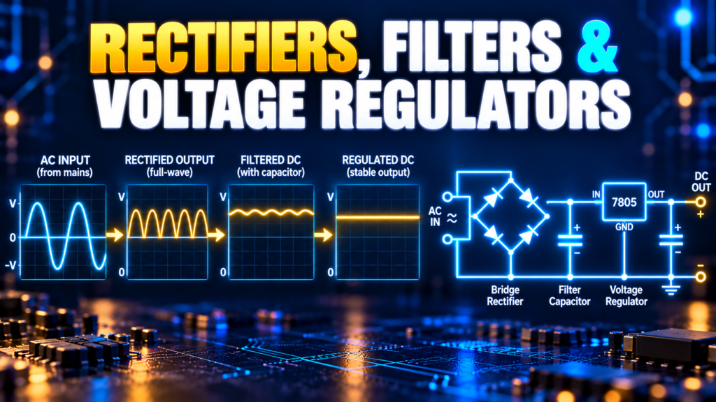
A rectifier, filter, and voltage regulator each solve a different part of the power-supply problem. The rectifier converts AC to pulsating DC, the filter reduces ripple, and the regulator keeps the output closer to a desired voltage as conditions change. This guide follows that path step by step.
Contents
- Power supply stages
- Rectifiers explained
- Smoothing filters
- Voltage regulators
- Comparing the stages
- Worked example
- Choosing components
- Safety and troubleshooting
- Questions and answers
How does a basic power supply work?
Many electronic devices need direct current, or DC, at a reasonably steady voltage. An AC source reverses polarity periodically. A simple transformer-based linear supply often contains these stages:
- A transformer changes the AC voltage and can provide isolation when specifically designed and rated for that purpose.
- A rectifier directs current so that the output has one main polarity.
- A filter reduces the variation, or ripple, in that pulsating output.
- A regulator controls the output voltage within its operating limits.
Not every supply follows this exact arrangement. A modern switching adapter uses additional high-frequency switching, control, and protection circuits. The four-stage model is still a useful starting point for understanding what each part of a supply does.
Use a certified, isolated low-voltage source for learning. Mains voltage can be lethal, and even a disconnected supply can contain charged capacitors. The calculations below describe the low-voltage side; they aren’t instructions for constructing or servicing a mains supply.
What is a rectifier?
A rectifier converts alternating current into a current that flows mainly in one direction through the load. Diodes are common rectifying components because they conduct readily when forward biased and oppose reverse current within their ratings.
Rectification alone doesn’t produce a perfectly flat output. The waveform still rises and falls, so it is often called pulsating DC. Its exact shape depends on the rectifier arrangement and the load.
Half-wave rectifier
A half-wave rectifier uses one diode to pass one half of the AC cycle and block the other. It is simple, but it uses only one half-cycle and leaves a relatively long interval between output pulses. A smoothing capacitor must cover that interval as it supplies the load.
For a 50 Hz input, the pulse repetition rate of a half-wave rectifier is 50 Hz. With a 60 Hz input, it is 60 Hz. This distinction matters when estimating ripple.
Full-wave bridge rectifier
A bridge rectifier uses four diodes. During each half-cycle, a pair conducts and directs current through the load in the same direction. Both halves of the input waveform contribute, so the output pulse rate is twice the AC frequency: 100 Hz from 50 Hz AC, or 120 Hz from 60 Hz AC.
In a standard bridge, current typically passes through two diodes at a time. Their forward drops reduce the available voltage. Those drops vary with current, temperature, and diode type, so the common “0.7 V per diode” approximation is only a starting estimate.
Centre-tapped full-wave rectifier
Another full-wave arrangement uses a centre-tapped transformer secondary and two diodes. Each half of the secondary supplies the load on alternate half-cycles. The transformer connections and voltage ratings differ from a bridge circuit, so the two arrangements aren’t directly interchangeable.
What does a smoothing filter do?
A smoothing filter reduces changes in the rectified voltage. A common basic filter places a capacitor across the output after the rectifier. Near a waveform peak, the capacitor charges. Between peaks, it supplies part of the load current and its voltage falls. The next peak replenishes the charge.
The remaining up-and-down variation is called ripple voltage. A larger capacitance, lighter load, or higher pulse frequency generally reduces ripple in a simple capacitor-input supply. The real waveform and charging current depend on transformer and diode resistance as well as the load.
Estimating capacitor ripple
For a rough estimate under approximately constant load, use:
ΔV ≈ I / (f × C)
Here ΔV is peak-to-peak ripple in volts, I is load current in amperes, f is the rectified pulse frequency in hertz, and C is capacitance in farads. This approximation assumes the capacitor discharges roughly linearly between charging peaks; it isn’t a complete transformer or diode design calculation.
At 0.1 A load, 100 Hz pulse frequency, and 1,000 µF (0.001 F), estimated ripple is 0.1 / (100 × 0.001) = 1 V peak-to-peak. At the same load and capacitance with half-wave rectification from 50 Hz AC, the estimate is about 2 V because the time between pulses is longer.
Real capacitors also have equivalent series resistance, ripple-current limits, leakage, and tolerances. An electrolytic capacitor is polarized: connecting it backwards or exceeding its voltage rating can cause failure. Select a voltage rating with suitable margin for the highest expected no-load voltage and transient conditions.
Other filter arrangements
Resistors, inductors, and capacitors can be combined into RC, LC, or multi-stage filters. These can reduce particular ripple components, but introduce tradeoffs such as voltage drop, heat, size, cost, and load-dependent behavior. A filter reduces unwanted variation; it doesn’t automatically guarantee a fixed output voltage.
What is a voltage regulator?
A voltage regulator controls output voltage using feedback or another reference mechanism. Within its specified input voltage, load, and temperature limits, it can make the output less sensitive to input and load changes. It cannot compensate indefinitely for an input that falls below its required operating range.
Linear regulators
A linear regulator acts like a controlled variable element between input and output. It is straightforward to use and can provide a low-noise output when properly designed. Its main drawback is heat: the approximate regulator dissipation is (Vin − Vout) × Iout, plus smaller losses associated with its own operating current.
For example, dropping 9 V to 5 V at 0.2 A produces approximately (9 − 5) × 0.2 = 0.8 W in the regulator. Whether that is safe depends on the package, heat sink, airflow, ambient temperature, and thermal resistance. A part with a nominal current rating of 1 A won’t necessarily deliver that current without overheating.
A linear regulator also needs input headroom. Its dropout voltage describes the minimum input-to-output difference needed under specified conditions. A low-dropout regulator can operate with less headroom, but the actual figure varies with load current and device. Input and output capacitors must match the datasheet’s recommendations, including any stability requirements.
Switching regulators
A switching regulator controls energy with a rapidly switched device and energy-storage components such as inductors or capacitors. A buck converter steps voltage down; a boost converter can step it up. Depending on design and operating conditions, a switching regulator can be much more efficient than a linear regulator when the voltage difference is large.
Switching supplies can introduce ripple and electromagnetic interference and require careful layout. Efficiency is not 100%, and it changes with input voltage, output current, and converter design. Some supplies combine a switching stage with a linear stage when both efficiency and a quieter output are needed.
Zener-based regulation
A Zener diode and series resistor can form a simple shunt regulator for small loads. The resistor must limit current, while the Zener conducts within its specified breakdown operating range. Output accuracy and efficiency are limited, and the circuit may stop regulating if load current becomes too high.
Rectifier vs filter vs regulator
| Stage | Main job | Typical parts | Key limit |
|---|---|---|---|
| Rectifier | Convert AC to pulsating DC | Diode or diode bridge | Current, reverse voltage and heat |
| Filter | Reduce ripple | Capacitor; sometimes resistor or inductor | Capacitance, voltage and ripple-current ratings |
| Regulator | Control output voltage | Linear or switching regulator | Input range, current, thermal and stability limits |
These stages complement one another. A bigger capacitor doesn’t replace a regulator when close voltage control is needed, and a regulator cannot work properly if the filtered input repeatedly falls below its minimum required voltage.
Worked example: a 5 V linear supply
Consider a teaching example with an isolated 9 V RMS, 50 Hz AC secondary, a full-wave bridge, a smoothing capacitor, and a 5 V linear regulator. Assume the secondary rating applies at its stated load and that two conducting diodes together drop approximately 1.4 V. The peak of an ideal sine wave is:
Vpeak = VRMS × √2 ≈ 9 × 1.414 = 12.7 V.
Subtracting the assumed diode drops gives roughly 11.3 V at the capacitor peak. This is an estimate, not a guaranteed voltage. Actual no-load transformer voltage can be higher, and transformer resistance, diode characteristics, mains variation, and load change the result.
If the load is 0.1 A and the capacitor is 1,000 µF, the simple ripple estimate above is about 1 V peak-to-peak at 100 Hz. A rough minimum between peaks would then be around 10.3 V under these assumptions. This appears to leave headroom for many 5 V linear regulators, but the designer must check the chosen regulator’s dropout, transformer regulation, tolerances, startup, and worst-case input conditions.
Using an illustrative average regulator input of 10.8 V, dissipation at 0.1 A is roughly (10.8 − 5) × 0.1 = 0.58 W. The average input is only an assumption here; measure or model the actual waveform for a real thermal design. Also verify capacitor voltage and ripple-current ratings, bridge surge capability, fusing, and protection before building anything.
How to choose the components
- Transformer or source: choose an appropriately rated, isolated supply with sufficient voltage and current at the intended load.
- Diodes: check average and surge current, reverse voltage, forward drop, and thermal conditions. Capacitor charging pulses can exceed the average load current.
- Capacitor: check capacitance tolerance, working voltage, ripple current, polarity, temperature, and lifetime.
- Regulator: check input range, dropout at load current, output current, heat, and required external capacitors.
- Protection: use the manufacturer’s recommendations for fuses, reverse current, overloads, and transient conditions.
Don’t choose parts solely from their largest headline number. A capacitor rated for a high voltage may still have inadequate ripple-current capability. A regulator rated for high current may overheat at the available input-to-output voltage difference.
Troubleshooting and safety
If a low-voltage supply has excessive ripple, first verify the load current, capacitor value and condition, rectifier connections, and AC source. If the regulated output is low, check the regulator input at the lowest point of its ripple, the load, and thermal conditions. An oscilloscope can reveal ripple that a DC multimeter reading hides.
Disconnect power before changing wiring, and verify that capacitors are discharged with an appropriate meter. Keep hands away from exposed mains connections. Mains equipment, high-energy capacitors, and damaged power adapters should be serviced only by a qualified person.
Frequently asked questions
Is rectified AC the same as smooth DC?
No. Rectification gives a waveform with one main polarity, but it still varies. Filtering reduces the ripple, and regulation can improve voltage stability when there is enough headroom.
Why is a full-wave bridge often preferred?
It uses both halves of the AC cycle and produces pulses at twice the input frequency. For a given simple capacitor and load, this can reduce ripple compared with half-wave rectification.
Does a larger capacitor always solve ripple?
A larger capacitance can reduce the estimated ripple, but it can also increase charging surge currents and isn’t a substitute for correct component ratings or regulation. The actual circuit imposes limits.
Why does a linear regulator get hot?
It dissipates much of the voltage difference between input and output as heat while supplying current. Calculate the expected loss and check the thermal design.
When reading a power-supply schematic, follow the energy path from source to load and identify each stage’s job. That makes it easier to see where ripple, voltage loss, and heat come from—and where to measure when the output isn’t right.


Comments
Comments are currently closed.