
RC Filters and Time Constants: A Beginner’s Guide
RC Filter and Time Constant Explained: Low-Pass, High-Pass, and Examples
A resistor and a capacitor can do more than sit quietly on a circuit board. Together, they can smooth a noisy signal, pass rapid changes, or create a useful delay.
An RC filter uses a resistor and capacitor to change how a circuit responds to different frequencies. The same components define an RC time constant, which tells you how quickly a voltage approaches a new value. Understanding both ideas makes sensor, audio, and timing circuits easier to read.
Key takeaways
- An RC filter changes signal strength gradually with frequency. It has no sharp on/off boundary.
- Cutoff frequency: fc = 1 / (2πRC). At cutoff, output is about 70.7% (−3 dB) of the passband value.
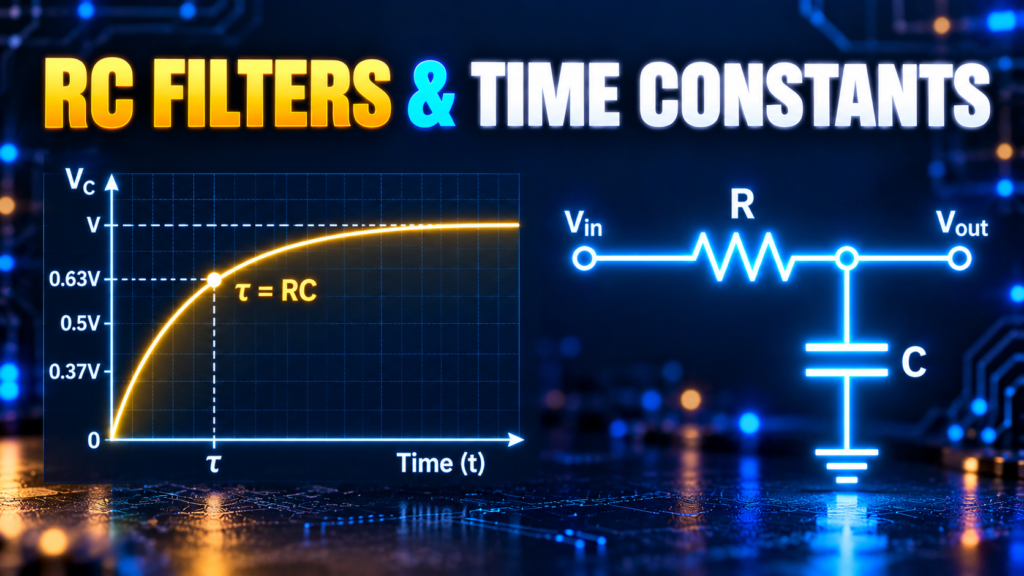
- Time constant: τ = R × C. After one τ, a charging capacitor reaches about 63.2% of its final value.
- Longer τ means lower cutoff: fc = 1 / (2πτ).
- Source impedance, load impedance, and component tolerance all shift real-world results.
Topics covered
- What is an electronic filter?
- A quick look at frequency
- Low-pass RC filter
- High-pass RC filter
- Low-pass vs high-pass compared
- RC time constant
- Cutoff frequency and time constant
- Worked example: selecting an RC filter
- Practical limitations and design tips
- How to test an RC filter
- FAQs
What Is an Electronic Filter?
A filter is a circuit that changes the relative strength or phase of different frequency components in a signal. A low-pass filter passes lower frequencies more readily than higher ones. A high-pass filter does the opposite.
“Pass” doesn’t mean wanted frequencies are unchanged, and “block” doesn’t mean unwanted ones vanish. A simple first-order RC filter changes gradually, with no sharp boundary between passage and rejection.
Filters appear in sensor inputs, audio circuits, power supplies, communication systems, and data acquisition. A capacitor across a rectifier output reduces ripple, and an RC stage in a signal path can reduce high-frequency noise, depending on the frequencies and the rest of the circuit.
A Quick Look at Frequency
Frequency is the number of cycles per second, in hertz (Hz). A 100 Hz sine wave completes 100 cycles each second. Real audio and noise signals are mixtures of many frequencies.
Capacitors oppose changes in voltage. In sinusoidal steady state, capacitive reactance has magnitude:
XC = 1 / (2πfC)
with f in hertz and C in farads. As frequency rises, reactance falls. At DC, an ideal capacitor stops conducting once the transient settles. Real capacitors have leakage, and at very high frequencies parasitic resistance and inductance also matter.
How a Low-Pass RC Filter Works
A passive low-pass filter puts a resistor in series with the signal and a capacitor from the output node to ground. The output is taken across the capacitor. This assumes a suitable source and a load that doesn’t disturb the circuit.
At low frequencies, the capacitor’s reactance is high, so the output follows the input. At higher frequencies, the capacitor gives changing current a lower-impedance path, reducing the output.
Cutoff Frequency Formula
For an ideal first-order RC low-pass filter with a low-impedance source and high-impedance load:
fc = 1 / (2πRC)
R is in ohms, C in farads, fc in hertz. At fc, the output is about 0.707 of the passband value, or −3 dB. It is a reference point on a gradual response.
Well above cutoff, an ideal first-order response falls about 20 dB per decade: a tenfold frequency increase cuts voltage amplitude to roughly one tenth. Near cutoff, use the full response or a simulation instead of this shortcut.
Low-Pass Example
R = 10 kΩ and C = 100 nF give RC = 10,000 × 0.0000001 = 0.001 s, so:
fc ≈ 1 / (2π × 0.001) ≈ 159 Hz
A sensor circuit might use this to reduce rapid fluctuations, but it also slows genuine changes. Choose the cutoff based on both the noise you want to reduce and the response speed you need.
How a High-Pass RC Filter Works
A passive high-pass filter swaps the components: the capacitor is in series with the input, the resistor connects the output node to ground, and the output is taken across the resistor. The same formula applies: fc = 1 / (2πRC).
At low frequencies, the capacitor’s high reactance reduces the output. At higher frequencies its reactance falls, so the output follows changes more closely. Once a DC input settles, the series capacitor blocks DC and the output approaches its reference voltage.
A coupling capacitor uses this behavior to pass an AC signal between stages while separating their DC operating points. The receiving stage still needs a proper bias or return path, because a capacitor alone doesn’t set the right input voltage.
High-Pass Example
The same 10 kΩ and 100 nF give an ideal cutoff near 159 Hz in the high-pass arrangement. The components are identical to the low-pass example; only the connection and output location change.
Far below cutoff, the ideal first-order response rises about 20 dB per decade. At cutoff, the output is about 0.707 of the high-frequency passband value. Source and load impedances can shift these results.
Low-Pass vs High-Pass RC Filters
| Feature | Low-pass | High-pass |
|---|---|---|
| Arrangement | Series R, capacitor to reference; output across C | Series C, resistor to reference; output across R |
| Passes more readily | Lower frequencies | Higher frequencies |
| DC behavior after settling | Output follows a DC input (high-impedance load) | Output approaches the reference |
| Common use | Smoothing, noise reduction | AC coupling, rejecting slow changes |
Both circuits affect phase as well as amplitude. They are called passive because they need no amplifier, and in these ideal arrangements a passive RC stage cannot give voltage gain.
What Is an RC Time Constant?
The RC time constant, τ (tau), is resistance times capacitance:
τ = R × C
With R in ohms and C in farads, τ is in seconds. For 10 kΩ and 100 nF, τ = 0.001 s (1 ms). It describes how quickly a first-order RC circuit responds to a step change.
Charging a Capacitor
An initially uncharged capacitor connected through a resistor to an ideal DC source VS charges as:
VC(t) = VS × (1 − e^(−t/RC))
| Time | Charge reached |
|---|---|
| 1τ | ≈ 63.2% |
| 2τ | ≈ 86.5% |
| 3τ | ≈ 95% |
| 5τ | ≈ 99.3% |
The capacitor approaches its final value asymptotically; it never reaches it at an exact finite time. For a 5 V step with τ = 1 ms, the ideal voltage is about 3.16 V after 1 ms and 4.97 V after 5 ms. The source must supply the initial current, and component voltage and power ratings must be adequate.
Discharging a Capacitor
Discharging from V0 through a resistor toward zero follows:
VC(t) = V0 × e^(−t/RC)
After one τ, about 36.8% of the initial voltage remains. After five τ, about 0.7% remains. A real circuit may discharge toward a non-zero voltage, and several resistances may shape the effective time constant. Use the resistance seen by the capacitor, with independent sources set to their inactive values.
How Are Cutoff Frequency and Time Constant Related?
For the ideal first-order RC circuits above:
fc = 1 / (2πτ)
A longer time constant means a lower cutoff frequency. This links the time-domain view (how fast a step settles) to the frequency-domain view (how sine waves of different frequencies are treated).
That tradeoff matters when a sensor needs both noise reduction and speed. Increasing R or C lowers the cutoff and reduces higher-frequency content, but it also lengthens τ and slows the response to sudden changes.
Worked Example: Selecting an RC Filter
A slowly changing sensor signal needs an ideal low-pass cutoff near 10 Hz. Pick R = 10 kΩ and solve for C:
C = 1 / (2π × 10,000 × 10) ≈ 1.59 µF
A standard 1.5 µF capacitor gives:
- fc ≈ 10.6 Hz
- τ = 10,000 × 1.5 µF = 15 ms
- Settling to within about 1% of the final value after roughly 4.6τ, or 69 ms
This is a starting point. A sensor with significant output resistance adds to the effective series resistance, and a low-impedance next stage loads the filter. Capacitor tolerance, leakage, voltage rating, and signal range also change the result, so check the circuit with the real source and load.
Practical Limitations and Design Tips
- Account for loading. The cutoff formula assumes a low-impedance source and a high-impedance load. A buffer can help.
- Check tolerance. Actual R and C differ from nominal values, so the cutoff is approximate.
- Use suitable capacitor ratings. Verify voltage, polarity, leakage, temperature range, and dielectric behavior.
- Watch resistor noise and input bias. Very large resistances can add error or noise in sensitive circuits.
- Don’t treat ripple as all noise. One RC stage rolls off gradually and may not reject every unwanted frequency.
- Mind the signal range. A high-pass stage often needs a bias point with a single-supply amplifier or ADC.
If the filter feeds an ADC, the converter’s sampling circuit draws brief charging currents. Check the datasheet for source-impedance and acquisition-time limits. A filter that looks right at DC can still cause measurement errors if the sampling capacitor doesn’t settle in time.
How to Test an RC Filter
Frequency test. On a safe low-voltage bench, apply a known sine wave and compare input and output amplitudes at several frequencies. Near the calculated cutoff, the ideal output should be about 70.7% of the passband amplitude. Account for instrument loading and the generator’s output impedance.
Time-domain test. Apply a step or square wave and watch the capacitor voltage on an oscilloscope. Measure the time to reach about 63% of the final change. Keep probe and component voltage ratings within limits, and discharge capacitors safely before changing connections.
Frequently Asked Questions
Does a low-pass filter remove all high-frequency noise?
No. A first-order RC filter attenuates higher frequencies gradually. The amount depends on frequency relative to cutoff and on source and load impedances.
Is the cutoff frequency where the signal becomes zero?
No. At cutoff, the ideal first-order output is about 70.7% of the passband value (−3 dB).
What happens if I double the capacitor value?
With the same effective resistance, the time constant doubles and the ideal cutoff frequency halves. Tolerances and loading still apply.
Does five time constants mean a capacitor is completely charged?
In the ideal model it is about 99.3% of the way to its final value. It approaches the final value asymptotically.
What is the difference between a low-pass and high-pass RC filter?
They use the same parts, but a low-pass filter takes its output across the capacitor and passes low frequencies, while a high-pass filter takes its output across the resistor and passes high frequencies.
How do I calculate the cutoff frequency of an RC filter?
Use fc = 1 / (2πRC), with R in ohms and C in farads. Assume a low-impedance source and high-impedance load.
Conclusion
Start by identifying where the output is measured and how the capacitor is connected. Use τ = RC to estimate the time constant and fc = 1/(2πRC) for the ideal cutoff. Then check the source, load, and component ratings before relying on the result.


Comments
Comments are currently closed.