
What Is an Oscillator? The 555 Timer Explained
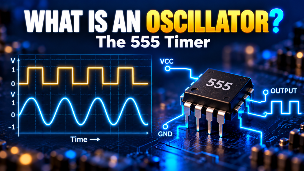
555 Timer and Oscillators Explained: Modes, Formulas, and Examples
A flashing LED, a simple alarm, and a clock circuit all need something to create repeated electrical changes. An oscillator provides that repetition, and the 555 timer is one of the most popular ways to build one.
This guide explains oscillator principles, the main oscillator types, the 555 timer’s pins and modes, worked calculations, and the practical limits you should know before building.
Key takeaways
- An oscillator produces a repeating signal from a DC supply. It does not create energy.
- Frequency is f = 1/T, and duty cycle is high time divided by period.
- The 555 works in three modes: astable (repeating pulses), monostable (one timed pulse), and bistable (set/reset).
- Basic 555 formulas are approximations. Component tolerance, supply, and loading shift the real result.
- For accurate timekeeping, use a crystal-based clock, not a basic RC-timed 555.
Topics covered
- What is an oscillator?
- Frequency, period, and duty cycle
- Types of oscillator
- What is a 555 timer?
- 555 timer pinout
- 555 operating modes
- Worked 555 examples
- Practical design tips
- How to troubleshoot a timer circuit
- FAQs
What Is an Oscillator?
An oscillator is an electronic circuit that produces a repetitive output without needing a repetitive input during normal operation. It draws energy from a power supply and converts some of it into a changing waveform.
Think of a kitchen timer that beeps repeatedly, or a microcontroller that needs a regular clock. In both, timing matters, though an indicator LED needs far less accuracy than a precision clock.
Oscillators can generate sine waves, square-like waves, pulses, and other shapes. The frequency may be set by resistors and capacitors, inductors and capacitors, or a quartz crystal.
Frequency, Period, and Duty Cycle
- Frequency is cycles per second, measured in hertz (Hz).
- Period is the time for one cycle. They are related by f = 1/T. A 0.5 s period gives 2 Hz.
- Duty cycle is the high time divided by the total period, as a percentage.
If a pulse is high for 0.2 s and low for 0.3 s, the period is 0.5 s and the duty cycle is 0.2/0.5 × 100 = 40%.
A square wave ideally has a 50% duty cycle. A rectangular wave can have any duty cycle. Real outputs also have finite rise and fall times, voltage limits, and noise.
Types of Oscillator
RC Oscillator
Resistors and capacitors set the timing. It is low cost and useful for audio-range signals, but frequency shifts with component tolerance and temperature, so it is a poor choice for precise long-term timing.
LC Oscillator
An inductor and capacitor form a resonant network. In an ideal LC circuit:
f = 1 / (2π√LC), with L in henries and C in farads.
LC oscillators are common in radio-frequency circuits. Real components have losses and parasitic effects, so the formula is a starting point, not a guarantee.
Crystal Oscillator
A quartz crystal’s mechanical resonance sets a stable frequency. Microcontrollers, clocks, and communication devices use them where stability matters. Even so, crystals have tolerance, temperature drift, and load requirements. Follow the manufacturer’s guidance for capacitors, layout, and drive level.
What Is a 555 Timer?
The 555 timer is an integrated circuit for timing and pulse generation. Inside, a resistor divider sets reference levels near one-third and two-thirds of the supply voltage. Two comparators watch the threshold and trigger inputs, and a latch controls the output and a discharge transistor.
With an external resistor and capacitor, it can generate repeated pulses, one timed pulse, or hold one of two states. Limits depend on the exact part: the original bipolar NE555 and modern CMOS versions differ in supply range, current draw, and output behavior. The formulas below are approximations for common circuits, so check the datasheet of your chosen device.
555 Timer Pinout
A standard eight-pin 555 uses these functions. Confirm the pinout and orientation in the datasheet before wiring.
| Pin | Name | Function |
|---|---|---|
| 1 | Ground | Supply reference |
| 2 | Trigger | A sufficiently low voltage starts the timing action |
| 3 | Output | Output signal within its specified drive limits |
| 4 | Reset | Active-low input that forces a reset |
| 5 | Control voltage | Access to an internal reference; a small capacitor to ground reduces noise |
| 6 | Threshold | Ends the timing interval when the timing voltage rises enough |
| 7 | Discharge | Internal transistor that discharges the timing capacitor |
| 8 | VCC | Positive supply |
Do not leave the reset pin unconnected and assume it behaves. Also, the output is not an unlimited power source: an LED needs current limiting, and a motor or relay needs a proper driver and inductive-load protection.
555 Timer Operating Modes
Astable Mode (Repeating Signal)
The output switches repeatedly between high and low as the timing capacitor charges and discharges through the resistor network. For the common two-resistor circuit with RA, RB, and C (ohms, farads, seconds, hertz):
- High time: tH ≈ 0.693 (RA + RB) C
- Low time: tL ≈ 0.693 RB C
- Frequency: f ≈ 1.44 / [(RA + 2RB) C]
Because RA adds to the high time only, this standard circuit’s high time is always longer than its low time, so it cannot give exactly 50% duty cycle. Modified circuits can change this.
Monostable Mode (One Timed Pulse)
The timer has one stable state. A trigger starts a single pulse, and a resistor and capacitor set its length:
t ≈ 1.1 R C
Use it to hold an indicator on briefly after a button press. Trigger duration, reset, supply, and capacitor leakage all affect real behavior.
Bistable Mode (Two Stable States)
The internal latch holds either state until a trigger or reset changes it. This gives a simple set/reset control without a charge-and-discharge timing cycle.
555 Operating Modes Compared
| Mode | Output behavior | Typical use |
|---|---|---|
| Astable | Repeated pulses | LED flasher, simple tone |
| Monostable | One timed pulse after a trigger | Short delay, pulse extension |
| Bistable | Two stable states | Simple set/reset control |
Choose the mode by the behavior you need, not just the frequency. If you need accurate timing across temperature and long periods, a crystal-controlled microcontroller or dedicated timing device is a better fit.
Worked 555 Timer Examples
Astable Frequency Calculation
Let RA = 10 kΩ, RB = 47 kΩ, and C = 10 µF.
- tH ≈ 0.693 × 57,000 × 0.00001 ≈ 0.395 s
- tL ≈ 0.693 × 47,000 × 0.00001 ≈ 0.326 s
- Period ≈ 0.721 s, so f ≈ 1.39 Hz
- Duty cycle ≈ 0.395 / 0.721 × 100 ≈ 55%
That is a pleasant LED flash rate, but expect variation from tolerance, leakage, and the timer’s characteristics. Electrolytic capacitors often have wide tolerances. For a repeatable frequency, measure the output and consider a tighter-tolerance capacitor or an adjustable component.
Monostable Pulse Calculation
For R = 100 kΩ and C = 10 µF:
t ≈ 1.1 × 100,000 × 0.00001 = 1.1 s
This is a nominal estimate. Verify that leakage, trigger conditions, and supply meet your part’s requirements.
In both examples, observe polarity on polarized capacitors and choose an adequate voltage rating. Keep the initial charging current and discharge pin current within the device’s limits.
Practical 555 Timer Design Tips
- Read the exact datasheet. Bipolar and CMOS versions differ in supply, output, and timing requirements.
- Bypass the supply. Place the recommended decoupling capacitor close to the supply pins, and follow the control-pin guidance.
- Pick sensible timing values. Very large resistances or leaky capacitors hurt accuracy, and very small resistances can exceed current limits.
- Plan the load. Check output levels at the real load current, and use a driver for heavier loads.
- Protect inductive loads. Relays and motors need a driver and flyback protection.
- Expect tolerance. Resistor and capacitor variation, temperature, and supply changes all shift the period.
For an LED, add a series resistor sized from the supply, LED forward voltage, output voltage under load, and desired current. Never connect an LED straight across the output.
How to Troubleshoot a Timer Circuit
- Check the supply voltage at the IC pins and confirm the package orientation.
- Verify the trigger, threshold, discharge, and reset connections against the datasheet circuit.
- Check resistor and capacitor values, and electrolytic polarity.
- Use an oscilloscope to view the timing capacitor and output. A slow multimeter may hide oscillation or show only an average.
- Remove the load if safe. An overloaded output can make a correctly timed circuit look faulty.
Use a safe low-voltage supply, disconnect power before rewiring, and make sure capacitors are discharged. For circuits that switch mains devices, use a properly designed isolated interface and get qualified help.
Frequently Asked Questions
Does an oscillator create energy?
No. It uses energy from the power supply to sustain a repetitive signal. Real components have losses, so it must keep receiving energy.
Can a 555 timer generate a sine wave?
Its common astable output is a pulse waveform. Producing a clean sine wave needs extra filtering or a different oscillator design.
Is a 555 timer accurate enough for a clock?
It gives a rough timing signal, but RC tolerance and drift make a basic 555 oscillator unsuitable for accurate timekeeping. A crystal-based clock is usually better.
Can a 555 output power a motor directly?
Don’t assume so. Startup current and voltage spikes can exceed the timer’s limits. Use a rated driver, a separate supply where appropriate, and inductive-load protection.
Why is my 555 frequency different from the calculation?
Check component tolerances, capacitor leakage, wiring, supply voltage, loading, and the specific timer’s specifications. The formulas are approximations for one circuit.
What is the difference between astable and monostable mode?
Astable mode produces a continuous train of pulses. Monostable mode produces a single pulse of fixed length each time it is triggered.
Conclusion
Start by defining the waveform, frequency, and accuracy you need. A 555 timer is an excellent tool for learning pulses and delays, while crystals and other oscillator circuits serve applications that need different waveforms or tighter timing. Use the formulas as a starting point, then measure and adjust the real circuit.


Comments
Comments are currently closed.