
What Is Electrical Resistance? Formula, Types and Uses
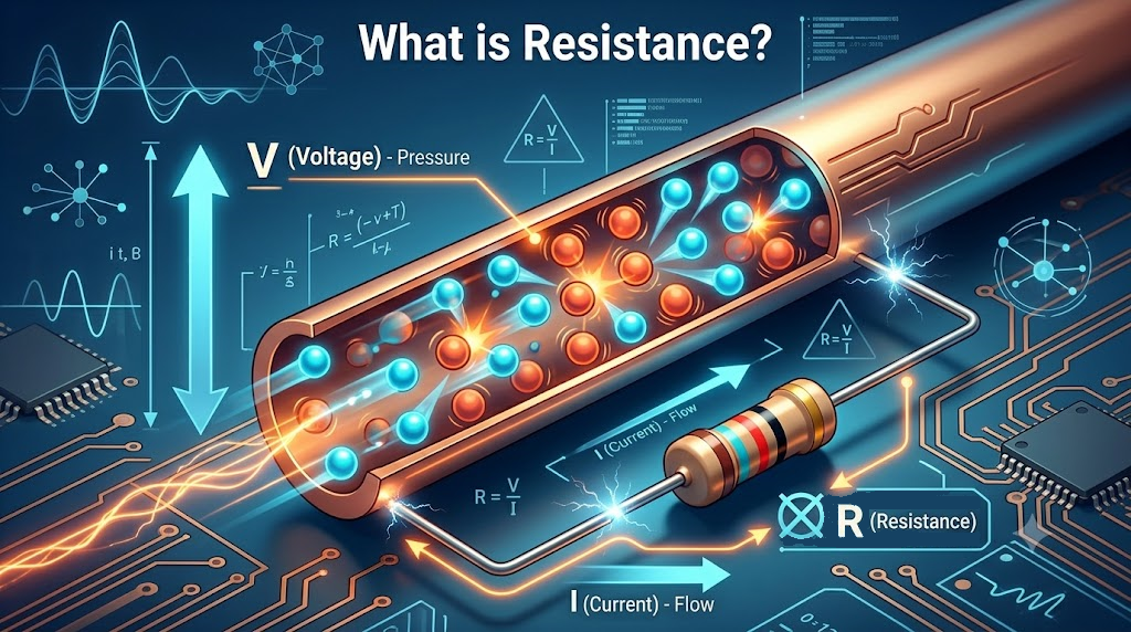
A tiny resistor can keep an LED working—or leave it burned out. The difference often comes down to choosing the right electrical resistance.
Electrical resistance is the opposition a component or material offers to electric current. Once you understand it, you can calculate current, choose resistors, and explain why some parts get hot.
What is electrical resistance?
Electrical resistance tells you how much voltage you need to drive a given current through a component. Its symbol is R, and its SI unit is the ohm (Ω).
A component has a resistance of 1 Ω when 1 V across it produces 1 A of current. You’ll also see kilohms and megohms: 1 kΩ = 1,000 Ω, and 1 MΩ = 1,000,000 Ω.
At the same applied voltage, a higher resistance means a lower current. Copper wires have low resistance; insulating materials such as rubber have very high resistance under normal conditions.
Resistance and resistivity aren’t the same
Resistance describes a particular wire or component. Resistivity, written as ρ, describes a material at a given temperature and is measured in ohm-metres (Ω·m).
Two copper wires can have different electrical resistance because their lengths or thicknesses differ, even though their material resistivity is the same.
Electrical resistance formula and examples
The basic electrical resistance formula is R = V / I, where V is voltage in volts and I is current in amperes.
You can rearrange it as V = IR or I = V / R. For an ohmic component, current is proportional to voltage while temperature and other physical conditions remain constant.
Don’t assume every device has a constant resistance. Diodes and heating lamp filaments, for example, don’t follow one constant-resistance relationship across their operating range.
Example: calculate resistance from voltage and current
- A resistor has 12 V across it and carries 0.02 A.
- Use R = V / I.
- R = 12 / 0.02 = 600 Ω.
If that resistance stays constant, applying 6 V gives I = 6 / 600 = 0.01 A, or 10 mA.
Example: choose an LED resistor
Suppose you have a 5 V supply, an LED with an assumed 2 V forward drop, and a target current of 10 mA.
- Voltage across the resistor: 5 − 2 = 3 V.
- Required resistance: 3 / 0.01 = 300 Ω.
- Resistor power: 3 × 0.01 = 0.03 W.
A common 330 Ω value gives about 9.1 mA under those assumptions. Check the LED datasheet and select a resistor power rating with suitable margin; the actual current changes with supply voltage and LED forward voltage.
What affects electrical resistance?
For a uniform wire with a constant cross-sectional area, use R = ρL / A. Here, L is length in metres and A is area in square metres.
- Length: double the length and you double resistance, if everything else stays the same.
- Cross-sectional area: double the area and you halve resistance. Doubling a round wire’s diameter makes its area four times larger.
- Material: copper has lower resistivity than nichrome at comparable temperatures.
- Temperature: most metals increase in resistance as they warm up.
Temperature behaviour depends on the material. NTC thermistors decrease in resistance as temperature rises; PTC thermistors increase. You can’t apply one temperature rule to every component.
Types of resistors compared
When people discuss types of electrical resistance, they often mean resistor types. Resistance is the property; a resistor is a component designed to provide it.
| Type | How resistance behaves | Typical use |
|---|---|---|
| Fixed resistor | Has a nominal value with tolerance and temperature variation | Current limiting and bias circuits |
| Potentiometer | Adjustable; three terminals allow voltage division | Volume or reference-level control |
| Rheostat | Adjustable resistance using two terminals | Current adjustment within its ratings |
| Thermistor | Changes strongly with temperature | Temperature sensing or inrush limiting |
| Photoresistor (LDR) | Usually decreases as illumination increases | Light-sensing circuits |
Fixed resistors include carbon-film, metal-film, and wirewound designs. Choose by resistance, tolerance, power rating, and operating conditions—not just package size.
Electrical resistance in series and parallel
Series: add the values
Resistors connected end to end carry the same current. Their total is Rtotal = R1 + R2 + ….
For example, 100 Ω and 200 Ω in series give 300 Ω. Each resistor’s voltage drop depends on its resistance and the shared current.
Parallel: add the reciprocals
Parallel branches share the same voltage. Use 1 / Rtotal = 1 / R1 + 1 / R2 + ….
Two 100 Ω resistors in parallel give 50 Ω. For positive, finite resistor values, the equivalent electrical resistance is lower than the smallest branch resistance.
Practical uses of electrical resistance
You use electrical resistance whenever you need to control current, create a signal voltage, or turn electrical energy into heat.
- LED current limiting: a series resistor sets an approximate operating current.
- Voltage division: two resistors provide a fraction of the input voltage. A connected load can change that voltage.
- Pull-up and pull-down circuits: resistors give digital inputs a defined default level.
- Heating: kettles and irons use resistive elements to produce useful heat.
- Current sensing: a known low-value shunt creates a measurable voltage drop.
A resistor alone isn’t a regulated power supply, and it doesn’t guarantee protection against every overvoltage or fault. Its usefulness depends on the whole circuit.
Power loss and resistor ratings
For a resistor, electrical power becomes heat. Calculate it with P = VI = I²R = V²/R, using volts, amperes, ohms, and watts.
A 100 Ω resistor carrying 0.1 A dissipates 1 W. A 0.25 W part would be overloaded; choose a suitably rated component and follow its temperature-derating guidance.
In wiring, unwanted electrical resistance causes voltage drop and heat. At a fixed current, a higher resistance means greater I²R loss. At a fixed voltage across a resistor, however, power decreases as resistance increases.
How to measure electrical resistance
A digital multimeter measures resistance by applying a small test signal. Start with a loose resistor or an isolated, low-voltage circuit.
- Disconnect all power sources. Discharge capacitors using an appropriate procedure and verify the circuit is de-energized.
- Put the black lead in COM and the red lead in the V/Ω socket.
- Select Ω mode and a suitable range if your meter isn’t autoranging.
- Touch the probes to opposite ends of the resistor.
- Compare the reading with its nominal value and tolerance.
Other circuit paths can lower an in-circuit reading. You may need to disconnect one resistor lead to measure the component alone.
“OL” generally means the reading exceeds the selected range; an open circuit is one possible cause. Never measure resistance on an energized circuit.
Your next step: calculate, then check
Electrical resistance connects voltage, current, material properties, and heating. Start with R = V / I, then check whether the component’s resistance changes under its actual operating conditions.
Try measuring a loose 1 kΩ resistor with your multimeter. Then calculate its current and power at 5 V: you should get 5 mA and 0.025 W.



Comments
Comments are currently closed.