
How Does an Electric Motor Work? Principle, Types and Uses
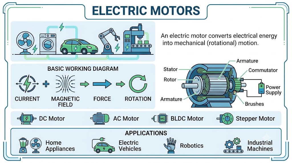
A fan starts spinning when you press a switch, but electricity doesn’t push the blades directly. A magnetic interaction turns the shaft inside the motor.
An electric motor converts electrical energy into mechanical motion. Most common designs use magnetic fields and current-carrying conductors to produce torque. The details change with the motor type, which is why the correct supply and controller matter.
Main parts of an electric motor
The stator stays still; the rotor turns. Depending on the design, permanent magnets or energized windings establish the magnetic fields involved.
- Stator: the stationary electromagnetic structure.
- Rotor: the moving assembly that develops torque.
- Shaft: transfers rotation to the load.
- Bearings: support the rotating assembly.
- Insulation and cooling: help the machine handle voltage and heat.
Some machines use brushes and a commutator. Others use electronic switching or an AC supply arrangement to maintain the field interaction needed for rotation.
How does an electric motor produce rotation?
A simple brushed DC motor offers a useful starting point:
- A DC source sends current through the armature winding.
- The winding’s conductors interact with the magnetic field.
- Forces on the conductors produce torque around the shaft.
- The commutator changes winding connections as the rotor turns.
- Torque accelerates the rotor until load and losses balance the operating conditions.
The switching keeps the torque useful as the rotor moves. Other electric motor designs achieve the required field relationship differently, so this sequence shouldn’t be applied unchanged to every machine.
Torque and speed aren’t the same
Torque describes turning effort; speed describes how quickly the shaft rotates. A load may need high starting torque even if its normal running power is modest.
Mechanical output power is P = Tω, with torque in newton-metres and angular speed in radians per second. A convenient equivalent is P = T × 2πn/60 when n is in rpm.
Common electric motor types compared
| Type | How switching or torque is arranged | Typical use |
|---|---|---|
| Brushed DC | Brushes and commutator switch rotor connections | Small tools and mechanisms |
| Brushless DC | Electronic commutation with a suitable drive | Fans, pumps, and motion systems |
| Induction | Stator field induces rotor current | Industrial drives and appliances |
| Synchronous | Rotor follows the rotating field synchronously | Efficient controlled drives |
| Stepper | Sequenced phase excitation produces commanded steps | Positioning mechanisms |
A stepper can lose steps if the demanded torque exceeds its capability. A brushless motor needs appropriate commutation; connecting DC directly to arbitrary phase wires won’t provide normal operation.
Why can starting current be high?
In a brushed DC motor, rotation generates back EMF that opposes the applied voltage. At standstill, this generated voltage is initially absent, so current can be much higher than during normal running.
Winding resistance, inductance, the source, and the driver limit the current. A stalled electric motor can overheat quickly if protection doesn’t act.
Induction machines also have startup behavior that must be considered. Use the motor and drive specifications rather than estimating startup demand from rated running power alone.
A mechanical power example
Suppose a shaft delivers 0.5 N·m at 1,200 rpm. Its output power is 0.5 × 2π × 1,200/60 ≈ 62.8 W.
If efficiency is assumed to be 80% at that operating point, electrical input is approximately 62.8/0.8 = 78.5 W. The difference becomes losses, mainly heat.
The efficiency assumption must come from suitable data or measurement. It won’t remain fixed across every speed and load.
Choosing and controlling a motor
- Match supply voltage, phase arrangement, and drive type.
- Check torque across the required speed range.
- Allow for starting, stalling, duty cycle, and cooling.
- Use suitable mechanical guarding and electrical protection.
- For low-voltage projects, use a rated driver rather than a GPIO pin.
A DC motor’s speed can often be adjusted with a suitable PWM drive. AC induction speed control commonly uses a variable-frequency drive. The correct method depends on the machine.
Begin with the load
An electric motor must match the mechanical job as well as the power source. Torque, speed, startup demand, and heat determine whether it will work reliably.
Take a motor datasheet and identify rated voltage, speed, torque, current, and duty. Then calculate its mechanical output power and compare it with the electrical input specification.

Comments
Comments are currently closed.