
Resistors, Capacitors, and Inductors: Component Basics
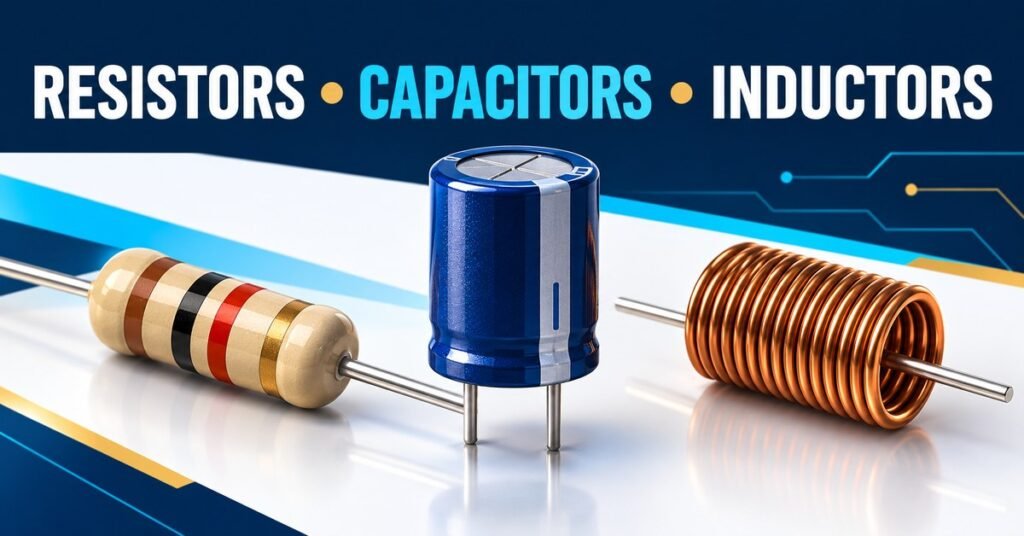
Open a small electronic device and you’ll usually find far more passive components than large chips. Those tiny parts quietly set currents, smooth supplies, and shape signals.
Resistors capacitors and inductors are the three basic passive components you should learn first. They handle electrical energy differently, which explains why swapping one for another rarely works.
A resistor dissipates energy, a capacitor stores energy in an electric field, and an inductor stores energy in a magnetic field. Let’s turn those descriptions into useful circuit instincts.
What does passive component mean?
A passive component doesn’t provide net energy gain on its own. It can dissipate energy or store energy temporarily, but it isn’t an independent power source.
This doesn’t mean every passive circuit only makes every voltage smaller. Resonance and transformer action can produce voltage magnification under suitable conditions while still respecting energy conservation.
Real components also include unwanted effects. A resistor has a little inductance and capacitance. A capacitor has losses. An inductor contains wire resistance and parasitic capacitance.
For beginner calculations, ideal models are useful because they isolate the main behavior. For a practical design, ratings and nonideal behavior explain why a correct-looking calculation may still produce a hot or unreliable circuit.
Think of the ideal model as your first sketch. The datasheet fills in the details needed to build the real thing.
Resistors: control current and dissipate energy
A resistor relates voltage and current through resistance. For an ideal resistor, V = IR, where resistance R is measured in ohms, written Ω.
Connect 5 V across a 1 kΩ resistor and current is 5/1000 = 0.005 A, or 5 mA. That relationship makes resistors useful for setting currents and forming voltage dividers.
The electrical energy becomes heat. Power is P = VI, which can also be written I²R or V²/R for a resistor.
At 5 V across 1 kΩ, dissipation is 25/1000 = 0.025 W. A suitable part must handle that power under its actual temperature and mounting conditions, with sensible design margin.
Resistance value alone isn’t enough. Tolerance tells you how far the actual value may differ from nominal, while temperature coefficient describes how resistance changes with temperature.
A practical resistor example: limiting LED current
Suppose a red LED has an approximate forward voltage of 2 V at your intended current. With a 5 V supply and a 10 mA target, the resistor must drop about 3 V.
Use R = (5 − 2)/0.010 = 300 Ω. A nearby standard value such as 330 Ω gives a slightly lower estimated current, about 9.1 mA under those assumptions.
The resistor dissipates roughly I²R, about 0.027 W for that estimate. Check the LED’s actual characteristics and the resistor’s rating rather than treating the assumed forward voltage as exact.
Don’t connect an LED directly across a stiff voltage source and expect it to select a safe current. The current-limiting element is doing essential work.
This example also shows why formulas belong with assumptions. Supply tolerance, LED temperature, and forward-voltage variation all change the actual current.
Capacitors: store energy in an electric field
A capacitor has conducting regions separated by a dielectric. Applying voltage causes equal and opposite charge to accumulate on its two sides.
Capacitance measures charge stored per unit voltage: C = Q/V. The unit is the farad, F. Practical values commonly use microfarads, nanofarads, and picofarads.
The ideal current relationship is i = C dv/dt. Current depends on how quickly the capacitor’s voltage changes. Its voltage cannot jump instantly without an impulse of current in the ideal model.
After a capacitor charges through a resistor from a DC source, its current falls toward zero. That is the basis of the useful statement that a capacitor blocks steady DC.
That statement needs context. During charging, current does flow, and real capacitors have leakage. Never assume a capacitor is discharged simply because a supply has been switched off.
Capacitance, timing, and stored energy
A resistor-capacitor network has time constant τ = RC. With R = 10 kΩ and C = 100 µF, the time constant is one second.
For a simple charging step from zero, capacitor voltage reaches about 63% of its final value after one time constant. After five time constants it is about 99.3% of the final value.
Stored energy is E = ½CV². A 100 µF capacitor charged to 10 V stores 0.005 J. The voltage is squared, so doubling voltage quadruples stored energy for the same capacitance.
Capacitors help with supply decoupling by supplying or accepting transient current close to a device. They also appear in filters, timing networks, coupling paths, and energy-storage circuits.
Choose voltage rating, capacitance tolerance, dielectric type, temperature behavior, ripple-current capability, and equivalent series resistance to suit the job. Polarized capacitors also require correct polarity and suitable bias conditions.
Inductors: store energy in a magnetic field
An inductor is often a coil of wire, sometimes wound around a magnetic core. Current through the coil creates a magnetic field.
Inductance L is measured in henries, H. Millihenries and microhenries are common in practical circuits. The ideal relationship is v = L di/dt.
That means an inductor opposes changes in current. Its current can’t jump instantly without an impulse of voltage in the ideal model.
With steady DC after transients settle, an ideal inductor has zero voltage across it. A real coil still drops voltage because its wire has resistance.
Inductors are useful in switching power supplies, filters, tuned circuits, and electromagnetic devices. Their behavior is especially valuable when a circuit needs to transfer energy efficiently between a source, storage element, and load.
Inductance, current limits, and flyback voltage
The magnetic energy stored in an ideal inductor is E = ½LI². For L = 10 mH and I = 0.5 A, stored energy is 0.00125 J.
If you abruptly interrupt that current, the inductor develops voltage that tries to keep it flowing. Without a controlled path, the voltage can become high enough to damage a switch or cause arcing.
A diode across a suitable DC relay coil gives current a path after the switch opens. Its orientation must block during normal energization and conduct during the release transient.
Other clamp arrangements release energy differently and can change relay turn-off speed. A flyback diode is common, but it isn’t the only possible protection method.
Watch both thermal current rating and saturation current. A magnetic core approaching saturation can lose much of its effective inductance, causing current to rise faster than the simple design calculation predicts.
Comparing their DC and AC behavior
Resistors ideally oppose current without storing recoverable energy. Capacitors and inductors exchange stored energy with the circuit, and their opposition to sinusoidal AC depends on frequency.
Capacitive reactance is Xc = 1/(2πfC). As frequency increases, ideal capacitive reactance decreases. Inductive reactance is Xl = 2πfL, which increases with frequency.
At 1 kHz, a 100 nF capacitor has reactance magnitude about 1592 Ω. A 10 mH inductor has reactance magnitude about 62.8 Ω.
Reactance isn’t the same as resistance. It changes the phase relationship between voltage and current in sinusoidal steady state, while an ideal reactive component has zero average real power loss.
Real parts eventually depart from these simple trends because parasitic effects matter. Don’t extend a low-frequency capacitor model indefinitely into radio-frequency operation.
What to check before choosing a part
Start with the required electrical value, then ask what stress the part will see. Maximum voltage, current, power, temperature, and frequency all matter.
For a resistor, check power derating and maximum working voltage as well as resistance. A tiny high-value resistor can exceed its voltage limit even when calculated power seems modest.
For a capacitor, check polarity, effective capacitance under DC bias, ripple current, and expected life. Two capacitors with the same printed value can behave differently in a power supply.
For an inductor, compare inductance at operating current, winding resistance, saturation, losses, and physical size. The nominal inductance measured at low current may not describe the loaded part.
Use the manufacturer’s conditions when comparing ratings. A current number without its temperature-rise or saturation definition can lead to a misleading comparison.
A useful troubleshooting routine
Disconnect the supply and discharge stored energy appropriately before resistance or continuity measurements. Measuring resistance in an energized circuit can damage a meter and produce meaningless results.
Inspect for cracked bodies, bulging capacitor tops, burnt board areas, and loose connections. Visual damage is a clue, although a good-looking part can still be faulty.
In-circuit measurements include other connected paths. If a resistor reads too low, a parallel branch may be responsible. Isolating one lead can help, when you have the skills to do it safely.
A basic capacitance meter doesn’t necessarily reveal excessive ESR or leakage. An inductor continuity check confirms a wire path but doesn’t establish its inductance or saturation behavior.
Record the symptom and operating conditions before replacing parts. A failed component may be the consequence of another fault, so replacing it alone might not solve the underlying problem.
Frequently asked questions
What is the main difference between resistors capacitors and inductors?
A resistor dissipates electrical energy as heat. A capacitor stores energy in an electric field, and an inductor stores it in a magnetic field. Their voltage-current relationships are therefore different.
Does a capacitor block all current?
No. Current flows while its voltage changes. An ideal capacitor blocks steady DC after charging, but supports time-varying current. Real capacitors also have leakage and other nonideal effects.
Why does an inductor produce a voltage spike?
Inductor current cannot change instantly in the ideal model. Opening its current path can therefore produce a large voltage as stored magnetic energy seeks another route. A suitable clamp limits that voltage.
Can I replace a resistor with a capacitor?
Usually not. A resistor sets a resistive voltage-current relationship, while a capacitor’s current depends on changing voltage. Their circuit roles and behavior are different even if their packages look similar.
Which ratings matter besides the printed value?
For resistors, power and voltage limits matter. Capacitors need suitable voltage, temperature, polarity, and ripple ratings. Inductors need adequate thermal and saturation current capability, with losses appropriate to operating frequency.
Quick reference and practice checklist
| Component | Ideal relationship | Energy behavior |
|---|---|---|
| Resistor | V = IR | Dissipates as heat |
| Capacitor | i = C dv/dt | Stores in electric field |
| Inductor | v = L di/dt | Stores in magnetic field |
Use this three-step routine when you review the examples:
- Write the nominal value and relevant units.
- Check electrical and thermal ratings.
- Compare the ideal model with the datasheet conditions.
Before moving on, check these details:
- Write units beside every number.
- State the assumptions behind your calculation.
- Check the result against the physical behavior described above.
Build your component instincts
Resistors capacitors and inductors become easier to understand when you ask where the energy goes. Is it becoming heat, entering an electric field, or entering a magnetic field?
Try calculating the LED resistor, the RC time constant, and the inductor energy above without looking at the answers. Then compare actual datasheets with the ideal models you’ve just used.


Comments
Comments are currently closed.