
What Is Inductance? Formula, Types and Applications
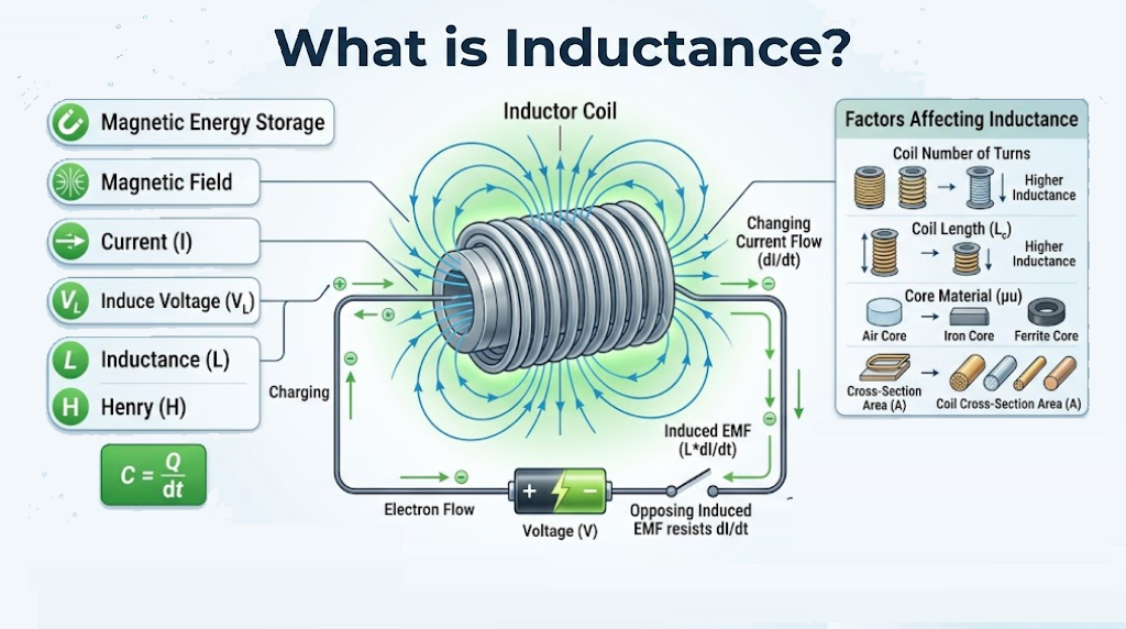
Switch off a relay coil, and the voltage across it can rise sharply. The stored magnetic energy still needs somewhere to go.
Inductance describes how changing current is linked to voltage through a magnetic field. An inductor resists a change in current, not current itself. This behavior makes it useful in converters, filters, transformers, and many sensing circuits.
Formula and units
For an ideal linear inductor with constant L, the terminal relation under the passive sign convention is v = L × di/dt. The sign convention takes current as entering the positively labeled terminal.
Inductance is measured in henries, or H. A millihenry is 10−3 H, and a microhenry is 10−6 H.
The equation says a faster current change requires a larger voltage. With finite voltage across an ideal inductor, its current can’t jump instantaneously.
What creates the magnetic field?
Current through a conductor creates a magnetic field. Winding the conductor into a coil links more of that field with the turns.
Turns, geometry, spacing, and core material affect inductance. A magnetic core can increase the value, but it introduces losses and a limit beyond which saturation becomes important.
Self and mutual coupling
Self-inductance relates a circuit’s changing current to its own flux linkage. Mutual inductance describes coupling between circuits through a shared magnetic field.
A transformer uses mutual coupling to transfer energy between windings. The amount of coupling depends on geometry and the magnetic structure; not all flux from one winding necessarily links the other.
Ideal inductor, real inductor, and capacitor
| Property | Ideal inductor | Real inductor | Ideal capacitor |
|---|---|---|---|
| Stored energy | Magnetic field | Magnetic field, with losses | Electric field |
| Rapid change | Current change requires voltage | Limited by ratings and parasitics | Voltage change requires current |
| Settled DC model | Zero voltage at constant current | Winding resistance causes voltage drop | Zero current at constant voltage |
| Frequency behavior | Reactance magnitude rises with frequency | Resistance and parasitic capacitance also matter | Reactance magnitude falls with frequency |
An actual coil is never a perfect short circuit at DC. Its wire resistance produces heating, and core behavior may change under load.
Calculate a current ramp step by step
Assume an ideal 10 mH inductor has a constant 2 V across it. Ignore resistance and saturation for this example.
- Convert 10 mH to 0.010 H.
- Rearrange the equation: di/dt = v/L.
- Calculate the slope: 2/0.010 = 200 A/s.
- For 1 ms, calculate Δi = 200 × 0.001 = 0.2 A.
- Add the change to the starting current.
If current starts at zero, it reaches 0.2 A after 1 ms in this ideal model. A real circuit needs current limiting and a component that stays within its ratings.
Energy and switching voltage
An ideal linear inductor stores E = ½LI². At 0.2 A, the 10 mH example stores 0.5 × 0.010 × 0.2² = 0.0002 J, or 0.2 mJ.
When a switch interrupts the path, current tries to continue. Voltage rises until another path conducts, a protective device acts, or insulation breaks down.
A suitable flyback diode can provide a path for a DC coil’s current. Other clamp arrangements can allow faster release. Protection must match current, energy, polarity, and switching requirements.
Where inductors are useful
- DC converters: controlled energy storage and transfer.
- Filters: frequency-dependent impedance.
- Transformers: magnetic coupling between windings.
- Sensors: detecting position or nearby conductive targets.
Check saturation current, thermal current rating, DC resistance, core loss, and self-resonant frequency. A nominal inductance value alone doesn’t establish suitability.
Connect the equation to the current path
Inductance links current change to voltage and magnetic energy. That explains both useful converter behavior and the need for switching protection.
Simulate the 10 mH example with a 1 V source, then predict the current change after 1 ms. Add winding resistance and compare the resulting ramp with the ideal calculation.



Comments
Comments are currently closed.