
What Is a Closed Circuit? Meaning, Examples, and Diagrams
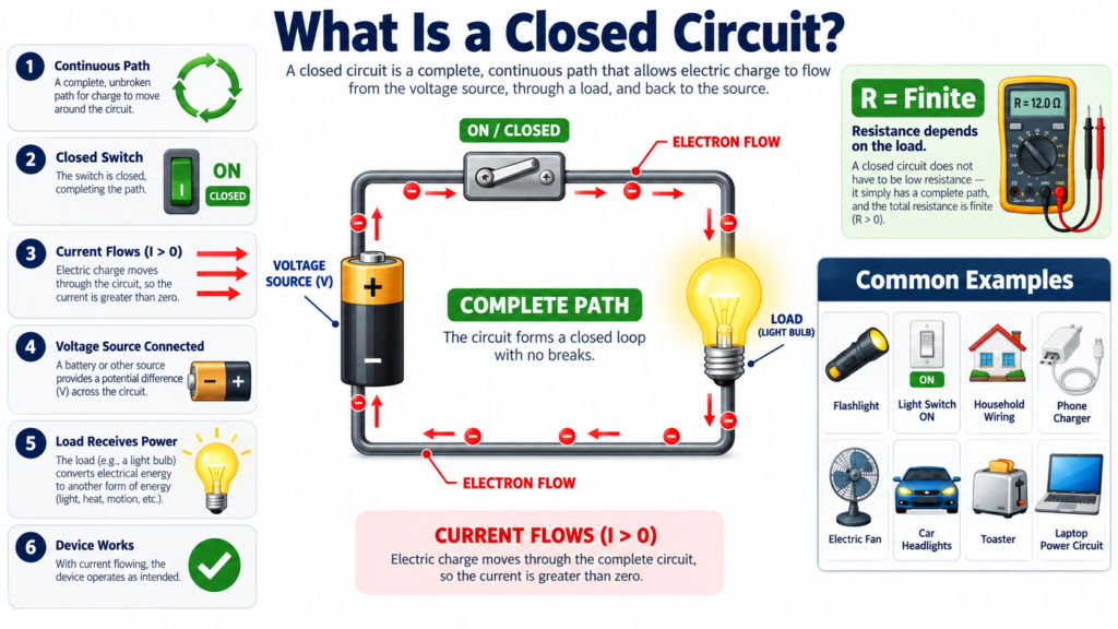
A closed circuit has a complete electrical path around which current can flow under suitable source and component conditions. In a simple battery, switch, and lamp arrangement, closing the switch completes the path and allows the lamp to receive power. Opening the switch interrupts the path and stops sustained current in that simple DC loop.
The phrase is easy to understand, but it is also easy to overinterpret. A complete path alone does not guarantee current: a source or another driving condition is still needed. A closed circuit also does not necessarily mean a short circuit. This guide explains the distinction with practical examples and basic calculations.
What makes a circuit closed?
A simple closed circuit includes a source, a load, conducting connections, and a continuous return path. The source maintains electrical conditions that can drive current. The load converts or stores energy, while conductors join the elements into a complete network.
A common beginner sketch shows a battery’s positive terminal connected to a resistor, followed by a return wire to the negative terminal. Both connections matter. Connecting only one side of the resistor to the battery does not form the same complete DC loop.
Real circuits can be more complex, with many branches and sources. One branch may be open while another remains a closed circuit. Always specify which path you mean instead of describing an entire large network as simply on or off.
Closed circuit versus open circuit
An open circuit contains an interruption in the path being considered. In a simple ideal steady DC loop, the current is zero. Voltage can still exist across the interruption, so an open switch is not proof that every nearby point is at zero potential.
A closed circuit has a continuous path, but its current depends on the source and total impedance. An ideal closed switch is represented as zero resistance and zero voltage drop. A real switch has contact resistance and a finite current and voltage rating.
| Feature | Open path | Normal closed path |
|---|---|---|
| Continuity | Interrupted | Complete |
| Simple DC loop current | Zero after transients | Set by source and load |
| Switch model | Very large resistance | Very small contact resistance |
| Voltage across switch | May be substantial | Near zero for a good closed contact |
The table describes idealized steady conditions. Capacitors, inductors, leakage, and switching transients can produce additional effects. The basic terms remain useful, but they should be applied with the circuit model and timescale in mind.
A closed circuit is not necessarily a short circuit
A normal closed circuit includes the intended load. A short circuit creates an unintended low-impedance connection between points at different potentials. It may bypass the load and cause excessive current rather than normal operation.
For example, a battery and a 100 ohm resistor form a complete controlled path. Replacing the resistor with a piece of wire changes that path dramatically. The source and wire impedance now largely determine the current, which can exceed safe limits for the source or conductors.
A short circuit is therefore a particular fault condition involving a low-impedance path, not another name for a healthy closed circuit. Both involve continuity, but their functions and consequences are different. Never demonstrate this distinction by deliberately shorting a battery or supply.
How current flows when a switch closes
When a switch completes a circuit, electromagnetic changes propagate through the system and the mobile charges already present respond. In metal conductors, electrons drift opposite to conventional current. The lamp does not need to wait for electrons to travel the full loop from the source.
The source transfers energy to the circuit, and the load converts that energy. A resistor produces heat, a lamp produces light and heat, and a motor can produce mechanical output plus losses. Charge itself is not consumed in the load.
For a simple resistive closed circuit, Ohm’s law connects current to the source voltage and total resistance. If the source is ideal and resistance remains fixed, doubling the voltage doubles current. Real sources and components introduce limitations that need to be considered in practical work.
Worked example: a resistor in a closed circuit
A 6 V ideal DC source is connected to a 300 ohm resistor through an ideal closed switch. Neglect wire resistance. Current is I = V/R = 6/300 = 0.02 A, or 20 mA.
The resistor voltage is 6 V, and its power is P = VI = 6 times 0.02 = 0.12 W. If the switch is opened, sustained loop current becomes zero in this simple model, and the resistor no longer dissipates that power.
Suppose the source has 10 ohms of internal resistance. The total becomes 310 ohms, and current is about 19.35 mA. The load voltage is then about 5.81 V. This illustrates how a more realistic source model changes the prediction slightly.
- Confirm that the source and load form a complete loop.
- Include all relevant series resistance.
- Calculate current using the total resistance.
- Calculate the voltage and power for each element.
- Check the effect of opening or closing the intended switch.
A calculation is only as meaningful as its model. An LED cannot simply replace the resistor while retaining the same fixed-resistance assumption. A motor needs a model that includes its operating behavior, and a capacitor introduces time dependence.
Closed paths in series and parallel networks
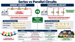
In a simple series chain, every component lies in the same path. Opening any connection interrupts current through the whole chain after transients settle. This is why one failed open component can stop an entire series branch.
In a parallel network, each branch can form its own complete path through the source. Opening one branch does not necessarily interrupt the others. Their behavior depends on whether the supply remains available and whether switching or protection affects the common connections.
A closed circuit can therefore exist in one branch even while another switch is open. Draw a complete route from one source terminal, through a branch, and back to the other terminal. If that route is interrupted, the particular branch is open.
This path-tracing approach is more reliable than judging by a switch’s location on the page. A switch drawn near the source might control every branch, while one drawn within a branch may control only a single load.
Does a closed circuit always carry current?
No. A complete loop containing only passive components and no stored energy can have zero current. A source with zero applied voltage across a resistor also gives zero current. Continuity permits current but does not create a driving condition by itself.
Two equal opposing sources can also produce zero net driving voltage in an ideal resistive loop. The path is complete, yet the calculated current is zero. This example separates topology, which describes connections, from excitation, which describes sources and initial energy.
A charged capacitor or energized inductor adds another possibility: stored energy can drive transient current even after a source is disconnected, provided an appropriate path remains. Sources, initial conditions, and component laws all help determine what happens.
Capacitors and inductors complicate the simple picture
A capacitor in a DC charging circuit allows transient current while its voltage changes. In the ideal final steady state, current becomes zero even though the wiring and switch remain connected. The dielectric is not a metallic conduction path between plates.
An inductor resists changes in current. If its current is interrupted, a large voltage may develop unless the circuit provides a suitable energy-transfer path. This is why relay coils and other inductive loads often require correctly designed suppression.
These examples do not make the term closed circuit useless. They show that a complete path is only the first step in analysis. Component behavior and the time after switching decide whether current is steady, changing, or zero.
Understanding continuity testing
A continuity tester checks whether a sufficiently low-resistance path exists according to the instrument’s threshold. A beep is useful information, but it is not proof that a circuit is correctly designed or safe to energize. Different meters use different thresholds.
Resistance and continuity tests should be made on isolated, de-energized equipment with stored energy safely dealt with under appropriate procedures. Never place a meter in continuity mode on an energized circuit. For beginners, use disconnected low-voltage teaching components.
Parallel paths can mislead a continuity check. A meter may find a route through another component even when the intended connection is open. Interpreting the reading requires knowledge of the schematic rather than relying on the sound alone.
Common misconceptions
- Closed does not mean zero resistance throughout the entire circuit.
- Open does not mean no voltage anywhere.
- A continuity beep does not identify every connection in the network.
- A complete path does not guarantee a nonzero current.
- A normal closed circuit and a short circuit are different conditions.
A good study exercise is to predict three things separately: whether a path is complete, whether a driving voltage or stored energy exists, and which element limits current. Those questions produce a more accurate explanation than saying electricity flows because the switch is on.
Frequently asked questions
Is a lamp circuit closed when the switch is on?
Usually, yes, if the lamp and connections are intact and the switch completes the intended path. A broken filament can leave the path open even when the switch is mechanically in the on position.
Can there be voltage in an open circuit?
Yes. A battery maintains terminal voltage without an external conducting loop. An open switch can also have voltage across its contacts. Voltage and current are separate quantities.
Is closed-loop control the same as a closed circuit?
No. Closed-loop control refers to feedback used to influence system behavior. A closed electrical circuit refers to a complete current path. Similar wording does not make them the same engineering concept.
Conclusion
A closed circuit provides a complete path in which current can flow when sources, stored energy, and component conditions support it. Distinguish continuity from excitation, and distinguish a healthy load path from a short circuit. Those distinctions make even simple switch-and-lamp examples valuable foundations for circuit analysis.

Comments
Comments are currently closed.