
AC vs DC: Key Differences Explained for Beginners
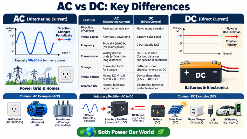
AC vs DC describes a difference in how electrical current behaves over time. Alternating current reverses direction, while direct current remains unidirectional. When discussing voltage, AC usually refers to a changing polarity and DC to a fixed polarity, possibly with variation in magnitude.
Both forms are central to electrical engineering. Batteries, electronic circuits, utility supplies, solar systems, and motor drives use AC, DC, or a combination connected by power converters. Rather than asking which is universally better, a useful comparison asks what each form does, how it is measured, and why a particular application chooses it.
AC vs DC: the main difference
A current waveform is a graph showing current against time relative to a chosen reference arrow. Positive values mean current follows that arrow; negative values mean it flows opposite to it. An AC waveform reverses sign, while a unidirectional DC waveform does not.
Ideal steady DC is drawn as a horizontal line. However, current can vary without reversing. A rectifier output that consists of positive pulses is commonly called pulsating DC. This is why saying that DC must always have a perfectly constant magnitude is too restrictive.
Many useful waveforms contain both a DC component and an AC component. A battery charger output, for example, may have a positive average value with superimposed ripple. Engineers describe both parts when the variation matters to the load.
What is alternating current?
Alternating current changes direction periodically in familiar power applications, although alternating signals need not be perfect sine waves. Utility and laboratory AC analysis often starts with a sinusoidal waveform because it is mathematically convenient and common in rotating electrical machines.
A sine wave can be written as i(t) = I_peak sin(2 pi f t plus phi). Frequency f is measured in hertz, period T equals 1/f, and phi sets the phase relative to a chosen time reference. Peak current is the largest magnitude reached.
A 50 Hz waveform completes 50 cycles each second, giving a period of 20 ms. A 60 Hz waveform has a period of about 16.67 ms. Frequency does not directly tell you amplitude, power, or the speed at which individual electrons travel.
What is direct current?
Direct current flows in one direction. Batteries supply DC at their terminals under normal discharge conditions, and many electronic devices require DC supply rails internally. Solar photovoltaic modules also produce DC, although their output depends on operating conditions and connected equipment.
A fixed-polarity DC supply can still change with time. Switching ripple, load transients, and battery discharge all produce variation. A well-regulated supply attempts to keep its output near a desired level across a specified operating range.
In AC vs DC discussions, it helps to distinguish a source from a load. A phone charger connects to an AC supply but provides a low-voltage DC output. Calling the phone an AC device merely because its charger plugs into an AC outlet misses the conversion inside the adapter.
AC vs DC comparison table
| Feature | AC | DC |
|---|---|---|
| Current direction | Reverses | Unidirectional |
| Typical beginner source | Signal generator | Battery or DC bench supply |
| Common waveform | Sinusoidal | Steady or pulsating |
| Ideal transformer use | Changing flux enables operation | Steady DC cannot sustain transformer action |
| Reactive behavior | Depends on frequency and phase | Transients matter; steady state differs |
| Common applications | Power networks and AC machines | Electronics, batteries, and DC links |
The table summarizes common patterns rather than rigid boundaries. Modern power electronics can transform DC voltage levels and control AC frequency. AC vs DC system choices therefore depend on conversion technology as well as the source and load.
RMS, peak, and average values
For a pure sine wave, RMS value equals peak magnitude divided by the square root of two. RMS relates a varying waveform to the same heating effect in an ideal resistor. A 10 V RMS sine wave has a peak magnitude of approximately 14.14 V.
Its average voltage over a complete cycle is zero, but its average power in a resistor is positive. Voltage and current reverse together in the ideal resistive case, so their product remains nonnegative. Zero average voltage does not imply zero useful energy transfer.
For a constant 10 V DC supply, peak magnitude, average value, and RMS value are all 10 V. For pulsating or distorted waveforms, those values differ and must be calculated from the actual waveform. Do not use the sine-wave RMS formula for every AC signal.
A worked AC vs DC resistor example
Connect an ideal 100 ohm resistor to 10 V DC. Current is 0.1 A, and power is 1 W. Now supply a pure sine wave of 10 V RMS across the same resistor. RMS current is also 0.1 A, and average power is again 1 W.
The instantaneous AC current is changing, even though its heating equivalent matches the DC example. Its peak is approximately 0.1414 A. The equal average heating does not mean a capacitor or motor would behave identically on the two supplies.
If the sine-wave source were specified as 10 V peak instead, its RMS value would be about 7.071 V. Average resistor power would then be 0.5 W. Always check whether a given AC amplitude is peak, peak-to-peak, or RMS before substituting it into a formula.
How capacitors and inductors respond
An ideal capacitor connected to steady DC becomes charged and carries no steady conduction current through its dielectric after transients settle. With AC excitation, its voltage keeps changing, so current continues according to i = C dv/dt.
An ideal inductor resists changes in current through v = L di/dt. In steady DC with constant current, its ideal terminal voltage is zero. Real inductors still have winding resistance, core losses, and operating limits, so they are not perfect short circuits physically.
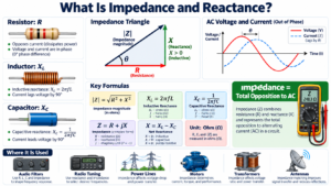
For sinusoidal steady state, inductive reactance increases with frequency while capacitive reactance decreases. This creates phase differences and frequency-dependent current. These effects explain why AC vs DC behavior cannot be predicted from resistance alone for many devices.
Why power systems use AC and DC
AC voltage can be stepped up or down using transformers, which helped make interconnected AC systems practical. Higher voltage allows lower current for a given transmitted real power, reducing conductor heating losses when other conditions are comparable.
DC transmission is also important. High-voltage DC links can offer advantages for certain long-distance routes, submarine cables, and connections between asynchronous AC systems. Converter stations and overall system requirements affect the economics, so there is no single transmission method best for every project.
This nuance matters in an AC vs DC comparison. It is inaccurate to say that DC cannot be transmitted over long distances or that only AC can operate at high voltage. The appropriate choice depends on the complete engineering system.
Converting between AC and DC
A rectifier converts AC into unidirectional output. Filtering smooths the waveform, and regulation controls the output within a specified range. An inverter converts DC into AC, often with controlled frequency, amplitude, and waveform quality.
A DC-to-DC converter changes one DC level to another by switching energy through inductive or capacitive components. It does not rely on feeding steady DC directly into a conventional transformer winding. Where transformers are used internally, switching creates the required changing flux.
A variable-frequency drive is a useful example. It can rectify an AC input to a DC link and then use an inverter to create controlled AC for a motor. A single piece of equipment can therefore contain both forms, each chosen for a particular function.
Practical considerations for students
Use a simulator or a supervised low-voltage signal generator to compare waveforms. An oscilloscope shows instantaneous shape and timing, while a multimeter provides values according to its measurement method and bandwidth. A meter reading alone may not reveal waveform distortion.
- Check whether the instrument measures AC, DC, or both components.
- Read amplitude units carefully before calculating current or power.
- Use appropriate input and grounding arrangements for the instrument.
- Compare identical loads when testing heating equivalence.
- Keep introductory experiments separate from mains installations.
Neither AC nor DC should be described as inherently safe. Hazard depends on voltage, current path, duration, available energy, frequency, and contact conditions. High-energy DC systems also present interruption challenges because there is no natural periodic current zero as in sinusoidal AC.
Frequently asked questions
Is battery current AC or DC?
A discharging battery normally supplies DC at its terminals. Electronics connected to the battery may convert that DC to AC internally, as an inverter does. The battery and converter output should be described separately.
Why do electronic devices use DC internally?
Many semiconductor circuits require stable supply polarities for biasing and operation. Their signals can still be alternating or time-varying. A DC-powered amplifier can process an AC audio signal without contradiction.
Can AC and DC have the same power?
Yes. Equal RMS voltage across the same ideal resistor gives equal average heating. For reactive or nonlinear loads, additional information about phase, waveform, and device behavior is needed.
Conclusion
AC vs DC is primarily about reversal of direction and polarity, with important consequences for measurement, component behavior, conversion, and system design. Learn to identify the waveform and its RMS or average values before calculating. That approach is more useful than assuming either form is universally superior.
Comments
Comments are currently closed.