
Series vs Parallel Circuits: Rules, Formulas, and Examples
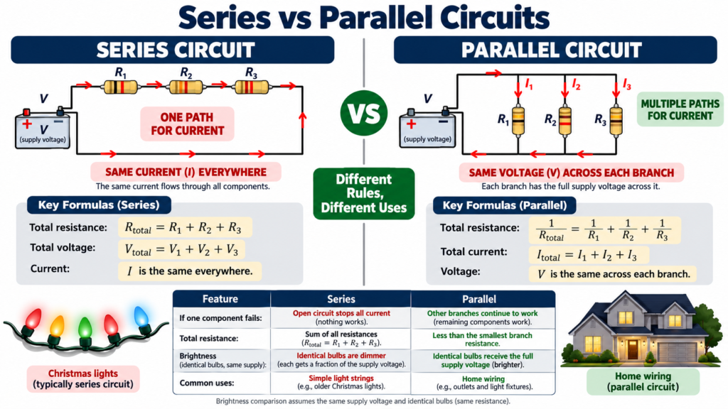
Series vs parallel circuits is a comparison of connection patterns. Components in a simple series path carry the same current because there is no branching between them. Components in parallel connect across the same two nodes and therefore have the same voltage across them.
Those two statements are more dependable than memorizing what a circuit looks like on a page. A drawing can be stretched, rotated, or rearranged without changing its electrical connections. By learning to identify nodes and current paths, you can calculate resistance, voltage drops, branch currents, and fault behavior even when a diagram looks unfamiliar.
Series vs parallel circuits: the core rules
| Property | Series resistors | Parallel resistors |
|---|---|---|
| Current | Same through each | Divides among branches |
| Voltage | Drops add to source voltage | Same across every branch |
| Equivalent resistance | Sum of resistances | Reciprocal sum relationship |
| Adding a positive resistor | Raises total resistance | Lowers total resistance when added as a branch |
| One branch opens | Interrupts the only path | Other intact branches may continue |
The final row assumes a suitable source remains connected and protection does not change the situation. Real circuits can contain controls and protective devices that affect the outcome. Series vs parallel circuits should first be understood in the ideal model, then interpreted with those practical details.
What makes components series-connected?
Two components are in series when the connection between them has no additional current-carrying branch. The current leaving the first must enter the second in the ordinary lumped circuit model. Their shared current is the defining feature.
For series resistors, R_total = R1 + R2 + R3 and so on. If 100 ohm, 200 ohm, and 300 ohm resistors are in series, the equivalent is 600 ohms. The source sees the same total voltage-current relationship as it would with one ideal 600 ohm resistor.
This equivalent does not preserve every internal detail. The individual resistors still have separate voltage drops and power dissipations. Equivalent resistance is a convenient view from the network terminals, not a claim that internal conditions are identical.
What makes components parallel-connected?
Parallel components share both connection nodes. Any ideal wire path joining one terminal of each defines one node, and the other terminals share the second node. Their voltage is equal even if the diagram places one branch far from another.
For parallel resistors, 1/R_total = 1/R1 + 1/R2 + 1/R3. For exactly two resistors, R_total = R1R2/(R1 + R2). With equal positive resistors, the equivalent is one resistor value divided by the number of branches.
The equivalent parallel resistance must be smaller than the smallest branch resistance when all branches have positive finite resistance. If your result is larger, inspect the algebra and units. This simple bound is one of the best checks in series vs parallel circuits problems.
Worked series-circuit example
Connect 2 kilohm and 4 kilohm resistors in series across an ideal 12 V source. Total resistance is 6 kilohms. Current is 12/6000 = 0.002 A, or 2 mA, through both resistors.
The voltage across the 2 kilohm resistor is 2 mA times 2 kilohms = 4 V. The voltage across the 4 kilohm resistor is 8 V. Their sum is 12 V, matching the source.
The higher resistance receives the larger voltage drop because both carry the same current. Their powers are 8 mW and 16 mW, respectively. Total resistor power is 24 mW, which equals source voltage times source current.
This example shows why saying that voltage is equal in a series circuit is generally wrong. Equal series resistors have equal drops, but unequal resistors divide the source voltage in proportion to resistance.
Worked parallel-circuit example
Connect 6 kilohm and 3 kilohm resistors in parallel across an ideal 12 V source. Each branch has 12 V across it. The branch currents are 2 mA and 4 mA, respectively, for a total source current of 6 mA.
The equivalent resistance is 12 V divided by 6 mA = 2 kilohms. Using the product-over-sum formula gives the same result: 6 times 3 divided by 6 plus 3, with consistent kilohm units, equals 2 kilohms.
The smaller resistance carries more current because the branch voltages are equal. Both branches conduct; current does not choose one and ignore the other. This corrects a common misunderstanding often expressed as electricity takes only the easiest path.
Voltage-divider and current-divider rules
For two series resistors with no additional load at their junction, the voltage across R2 is V_source times R2/(R1 + R2). The condition about loading matters. A new parallel load changes the effective lower resistance and therefore the output.
For two parallel resistors, the current through R1 is I_total times R2/(R1 + R2). The opposite resistor appears in the numerator because current divides inversely with resistance. Alternatively, calculate the shared voltage and then use Ohm’s law for each branch.
Do not apply a divider formula merely because the circuit contains two resistors. First confirm the required connection pattern. Series vs parallel circuits becomes easier when each formula is tied to its defining equal-current or equal-voltage condition.
Solving a mixed series-parallel circuit
Suppose a 2 kilohm resistor is in series with a parallel pair of 3 kilohms and 6 kilohms. The source is 12 V. Begin with the inner parallel pair: its equivalent is 2 kilohms.
The total resistance is then 2 kilohms plus 2 kilohms = 4 kilohms. Source current is 3 mA. The first resistor drops 6 V, leaving 6 V across the parallel pair.
The 3 kilohm branch carries 2 mA, and the 6 kilohm branch carries 1 mA. Their sum is 3 mA, matching the series current. These checks use both Kirchhoff’s current law and voltage law without needing a large set of simultaneous equations.
- Mark all electrically identical nodes.
- Identify a group that is definitely series or parallel.
- Replace that group with its equivalent resistance.
- Repeat until the source current can be calculated.
- Work backward to recover each branch current and voltage.
- Check current sums, voltage sums, and total power.
Some networks cannot be reduced this way. Bridge circuits and multiple-source networks may require nodal or mesh analysis. Recognizing that limit saves time compared with forcing an invalid series or parallel combination.
What happens when a component fails?
An open component in a simple series chain interrupts the only conducting path. Current stops throughout that chain in steady DC operation. An open branch in a parallel network usually leaves other branches connected to the source.
A shorted series resistor reduces total resistance and changes the remaining voltage distribution. A short directly across one branch of an ideal parallel network also connects the source terminals through that fault path. In practice, source impedance and protection determine the resulting fault current and disconnection.
These cases explain why the phrase one component fails is incomplete. An open failure and a shorted failure have different effects. Identify the failure mode and the nodes involved before predicting what the circuit does.
Real applications and practical limits
Household loads are generally supplied in parallel so each can receive the intended supply voltage and operate independently. This is a conceptual description, not a guide to installation wiring. Protective earthing, neutral arrangements, switching, and protection require proper design.
Series connections are useful for voltage division, current sensing, and arranging components that must share a path. LED strings can be series-connected with suitable current control. Batteries can be placed in series or parallel only with appropriate matching, protection, and system design.
Real wires have resistance, so parallel loads may not receive perfectly identical terminal voltages when long cables are involved. A source also has finite capacity. Adding parallel loads increases demand and can cause voltage sag or trigger a current limit.
Common mistakes in series vs parallel circuits
- Combining components based only on their visual position.
- Assuming series voltage drops are equal with unequal resistors.
- Assuming parallel branch currents are equal with unequal resistors.
- Forgetting that an added meter or load can change the network.
- Applying product-over-sum to more than two resistors at once.
A useful exercise is to redraw the same circuit in several shapes while preserving node labels. If the equations change merely because the drawing changes, revisit the connections. Topology, rather than the shape of the sketch, determines the relationships.
Frequently asked questions
Why is parallel resistance smaller than every branch resistance?
Adding another positive-resistance branch gives current another conducting path. At the same applied voltage, total current increases. Since equivalent resistance is voltage divided by total current, it decreases.
Is current the same everywhere in a series circuit?
In the ordinary lumped model, components in the same unbranched series path carry the same current. If a branch is added at a junction, those components may no longer form a simple series pair.
Can a circuit contain both types of connection?
Yes. Many practical circuits combine series and parallel groups. Reduce only valid groups, and use Kirchhoff’s laws when straightforward reduction is not possible.
Conclusion
Series vs parallel circuits is best understood through current paths and shared nodes. Series elements share current; parallel elements share voltage. Use those facts to derive formulas, verify calculations, and predict faults, rather than relying on the appearance of a diagram.
Comments
Comments are currently closed.