
How Do Electronic Circuits Work? Components and Basics
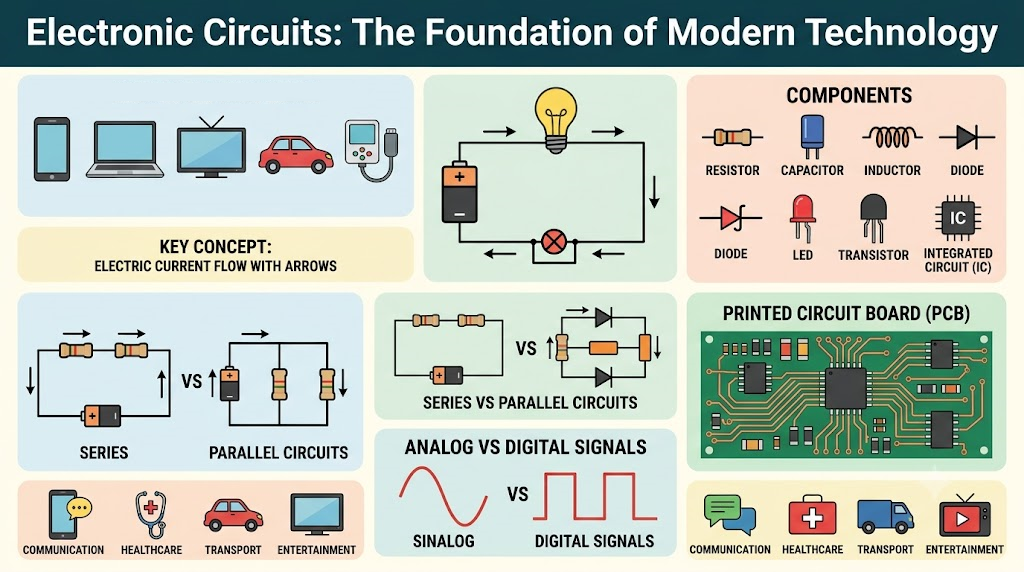
A few inexpensive parts can turn a button press into light, sound, or motion. The trick is controlling where electrical energy goes.
Electronic circuits connect components so they can process signals, control current, or transfer power. To understand one, identify its source, its current paths, and what each component does. You don’t need to memorize every symbol before you can follow a simple circuit.
Voltage, current, and resistance
Voltage is a potential difference between two points. Current is the rate of charge flow through a chosen cross-section. Resistance relates voltage and current for a component under its operating conditions.
For an ohmic resistor, V = IR. The relationship is useful, but it isn’t a fixed-resistance model for every device. Diodes and transistors have different behavior.
- Volt: measures potential difference.
- Ampere: measures current.
- Ohm: measures resistance.
- Watt: measures the rate of energy transfer.
Electronic circuits don’t normally consume charge as it passes through a load. A resistor transfers electrical energy mainly into heat; charge continues around the conducting path.
What the main components do
Passive components
Resistors limit or set currents and divide voltages. Capacitors store energy in electric fields, while inductors store energy in magnetic fields.
These parts also shape signals. Their response can depend on frequency, and real components have losses and ratings that ideal symbols don’t show.
Semiconductor components
Diodes have strongly directional current-voltage behavior. LEDs emit light when operated at suitable forward current. Transistors control current and can form switches or amplifiers.
Integrated circuits place many components together to perform more complex functions. They still need the correct supply, connections, and operating conditions.
Current paths in electronic circuits
In a simple series loop, the same steady current passes through each component. A break stops sustained current around that loop after switching effects settle.
Parallel branches connect across the same two nodes. Their currents can differ, and opening one branch needn’t stop another.
For electronic circuits with several sources or stored energy, trace each relevant path. A closed connection doesn’t guarantee nonzero current if there’s no driving condition.
Common circuit types compared
| Type | Purpose | Example |
|---|---|---|
| Analog | Processes continuously varying signals | A sensor amplifier |
| Digital | Uses defined logic ranges | A counter or logic controller |
| Power | Converts or controls energy | A DC voltage converter |
| Mixed-signal | Combines analog and digital functions | A digital temperature instrument |
These categories overlap. A single board can contain all four kinds of electronic circuits.
Build the calculation before the LED circuit
Assume a 5 V supply, an LED forward voltage of 2 V at the intended current, and a target current of 10 mA.
- Find the resistor voltage: 5 − 2 = 3 V.
- Calculate resistance: R = 3/0.010 = 300 Ω.
- Choose a nearby suitable value, such as 330 Ω.
- Estimate current: 3/330 ≈ 9.1 mA.
- Check resistor power: I²R ≈ 0.027 W.
- Verify LED polarity, component ratings, and supply tolerance.
The 2 V assumption must match the selected LED’s behavior. Put the resistor in series with the LED; don’t place an unprotected LED directly across the supply.
How to read and check electronic circuits
Start with the supply and reference node. Identify components, follow a complete path, and predict a few voltages and currents before measuring.
- Measure voltage across two points.
- Insert a current meter in series using the correct socket and range.
- Never place an ammeter directly across a source.
- Use resistance or continuity mode only on de-energized circuits with stored energy dealt with appropriately.
For beginner practice, use simulation or protected low-voltage equipment. Check transistor pinouts and polarized components before connecting power.
Trace one loop today
Electronic circuits become manageable when you connect each component’s job to a current path and an energy transfer.
Draw the LED circuit, calculate its expected current, and explain what changes when the switch opens. Then add a second parallel branch and predict its behavior separately.
Comments
Comments are currently closed.