
What Is Ohm’s Law? Formula, Examples, and Limitations
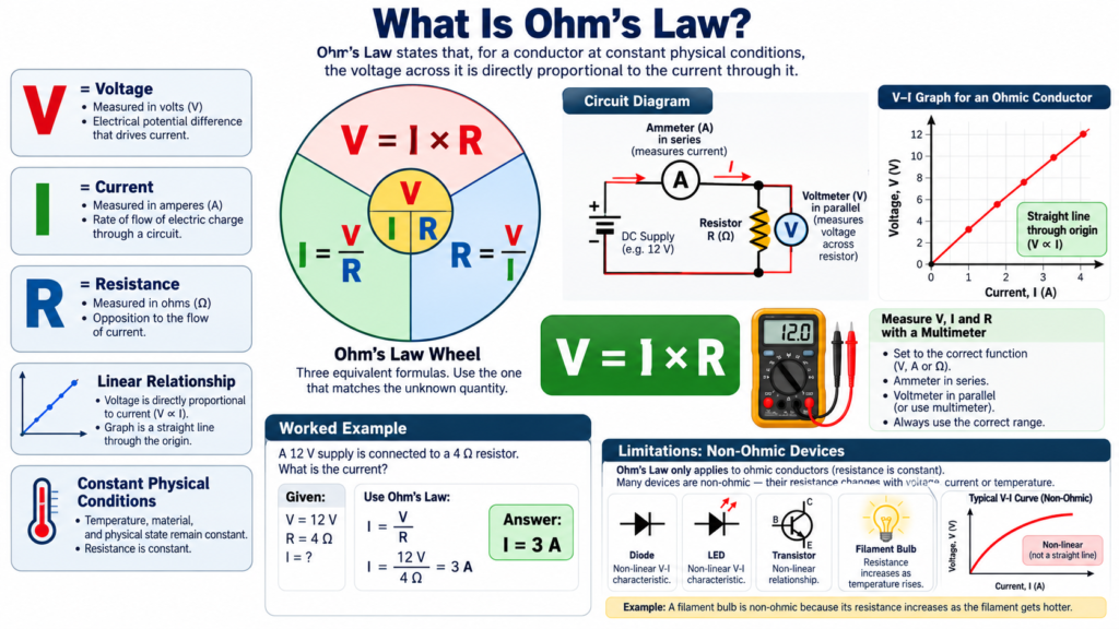
Ohm’s law states that the current through an ohmic conductor is proportional to the voltage across it when physical conditions, particularly temperature, remain constant. The familiar equation is V = IR, where V is voltage, I is current, and R is resistance. It is one of the first tools engineering students use to connect a circuit diagram to numerical predictions.
The equation is simple, but using it well requires more than moving symbols around. You need to identify the correct component, keep units consistent, recognize when a device is approximately ohmic, and check whether the resulting power is practical. Those habits make the difference between a correct calculation and a useful design decision.
Ohm’s law formula explained
The three common arrangements are V = IR, I = V/R, and R = V/I. They express the same relationship. Choose the arrangement that gives the unknown quantity directly, then substitute values with their units.
| Find | Equation | Required units |
|---|---|---|
| Voltage | V = IR | Amperes times ohms gives volts |
| Current | I = V/R | Volts divided by ohms gives amperes |
| Resistance | R = V/I | Volts divided by amperes gives ohms |
| Resistor power | P = I squared R | Amperes squared times ohms gives watts |
For example, apply 10 V across a 2 kilohm resistor. Convert 2 kilohms to 2000 ohms, then calculate I = 10/2000 = 0.005 A. The result is 5 mA. Keeping the conversion visible helps prevent a thousandfold error.
Alternatively, a resistor carrying 20 mA with a measured 6 V across it has an operating-point ratio of 300 ohms. If it is an ohmic resistor at stable temperature, that ratio stays approximately constant over its normal operating range. For a nonlinear device, one measured ratio does not establish Ohm’s law over other conditions.
What makes a component ohmic?
An ohmic component has a straight-line voltage-current characteristic through the origin under the stated conditions. Doubling voltage doubles current, so the ratio V/I remains constant. An ideal fixed resistor is the standard circuit model.
Real resistors approximate this behavior within limits. Temperature changes can alter resistance, and excessive voltage or power can damage the device. The law is therefore a model with an operating range, not permission to apply any voltage to any resistor.
A graph makes the idea clear. If current is on the vertical axis and voltage on the horizontal axis, the slope for an ohmic resistor is 1/R. A steeper line means greater conductance and lower resistance. If the axes are reversed, the slope becomes R instead.
Resistance and the physical conductor
For a uniform conductor, R = rho L/A, where rho is resistivity, L is length, and A is cross-sectional area. Longer wires have more resistance when material and area are unchanged. Increasing the cross-sectional area reduces resistance.
Resistivity depends on material and conditions. Metals generally become more resistive as temperature rises over ordinary temperature ranges. Other materials may behave differently. This is why resistance should not always be treated as a permanent property independent of the environment.
Ohm’s law and the geometry formula answer different questions. V = IR connects terminal voltage and current for an ohmic element. R = rho L/A estimates resistance from material and shape. You can use them together, but neither replaces the other.
For a cable, voltage drop depends on the complete current path. A two-wire DC circuit includes outgoing and return conductors. Ignoring the return length can lead to an underestimated resistance and a larger real voltage drop than expected.
Worked example: finding current and power
A 12 V ideal source is connected across a 120 ohm resistor. Ohm’s law gives I = 12/120 = 0.1 A. The power dissipated is P = VI = 12 times 0.1 = 1.2 W.
The same answer follows from P = V squared/R = 144/120 = 1.2 W. Agreement between the two methods checks the arithmetic. It does not mean a small resistor is suitable: a component rated below the required dissipation could overheat.
A practical resistor must have an appropriate power rating with allowance for its specified ambient conditions and derating requirements. The nominal resistance value alone is insufficient. Engineering calculations should always be followed by a check of component limits.
Suppose the source rises to 15 V while resistance stays 120 ohms. Current becomes 0.125 A, and power becomes 1.875 W. Voltage increased by 25 percent, but power increased by more than 56 percent because it depends on voltage squared for a fixed resistance.
Using Ohm’s law in series and parallel networks
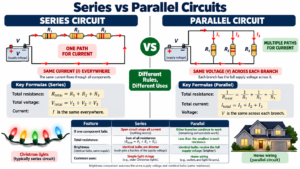
In a series network, the same current passes through each resistor. Add the resistances to find the total, calculate the current from the source voltage, and then calculate each resistor’s voltage drop using that same current.
For 100 ohm and 200 ohm resistors in series across 9 V, total resistance is 300 ohms and current is 30 mA. The drops are 3 V and 6 V. Their sum equals the source voltage, providing a useful consistency check.
In a parallel network, branches share the same two nodes and therefore the same voltage. A 100 ohm resistor and a 200 ohm resistor across 9 V carry 90 mA and 45 mA. Their combined source current is 135 mA.
Do not combine series and parallel rules by appearance alone. Two resistors drawn one above the other may not share both nodes. Identify connections first; then apply Ohm’s law to the appropriate branch or equivalent resistance.
Example: choosing an LED series resistor
Assume a low-voltage LED has an approximate forward drop of 2 V at the intended current, and the supply is 5 V. The series resistor must drop the remaining 3 V. For a target current near 10 mA, R = 3/0.010 = 300 ohms.
Choosing a commonly available 330 ohm value gives an estimated current of 3/330, or about 9.1 mA. Resistor dissipation is approximately 3 times 0.0091 = 0.027 W. The final choice must also respect LED ratings and expected supply and forward-voltage variation.
This example applies Ohm’s law to the resistor, not to a supposed fixed LED resistance. An LED has a nonlinear characteristic. Its forward drop is an approximation tied to current and temperature, so accurate design uses the device data and operating range.
Limitations of Ohm’s law
Diodes, transistors, and many other devices do not have a constant resistance over their operating range. An incandescent lamp also becomes strongly nonlinear across a large range because its filament heats substantially. Dividing V by I at one point gives a ratio, but does not prove proportionality everywhere.
Capacitors and inductors require time-dependent relationships. For an ideal capacitor, i = C dv/dt. For an ideal inductor, v = L di/dt. Their behavior cannot generally be described by a single real constant resistance.
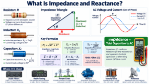
In sinusoidal steady-state AC analysis, the generalized phasor relationship is V = IZ, where Z is complex impedance. A resistor has Z = R, but reactive elements contribute frequency-dependent imaginary terms. This extension is powerful, provided the assumptions and notation are clear.
Ohm’s law also does not calculate a source’s available current by itself. Real batteries and power supplies have internal behavior, current limits, and operating constraints. An ideal source plus an unrealistically tiny resistor can produce a mathematically large result that the actual source cannot sustain.
A reliable problem-solving routine
- Mark the two terminals of the element being analyzed.
- Write the known voltage, current, or resistance beside it.
- Convert kilo, milli, and micro prefixes before substituting.
- Choose the correct rearrangement of V = IR.
- Calculate power and compare with component ratings.
- Check whether the result fits the circuit and model assumptions.
A rough estimate is useful before using a calculator. Ten volts across one kilohm should give milliamperes, not tens of amperes. If the result contradicts that scale, revisit units before assuming the circuit has unusual behavior.
For measurements, tolerances matter too. A resistor marked 1 kilohm with a specified tolerance need not measure exactly 1000 ohms. Supply accuracy, meter input resistance, and temperature can explain reasonable differences between calculated and measured values.
Frequently asked questions
Is Ohm’s law valid for AC circuits?
For an ideal resistor, instantaneous voltage and current satisfy v = iR. In sinusoidal AC networks containing reactance, use the phasor relationship with impedance. RMS magnitudes alone do not capture phase differences.
Does resistance change when voltage changes?
For an ideal ohmic resistor at fixed conditions, no. In a real component, extra voltage may cause heating, which can change resistance. Nonlinear devices can also change their V/I ratio for reasons other than heating.
Why is my measured current slightly different?
Check resistor tolerance, actual source voltage, meter burden voltage, contact resistance, and temperature. A difference does not automatically invalidate the law; it may show that the ideal model omitted a real effect.
Conclusion
Ohm’s law links voltage, current, and resistance for ohmic behavior under stated physical conditions. Use it with correct units, circuit connections, and power checks. Recognizing its limits is part of understanding the law, and it prepares you to analyze more realistic components with confidence.
Comments
Comments are currently closed.