
What Is Power Electronics? Devices, Types and Applications
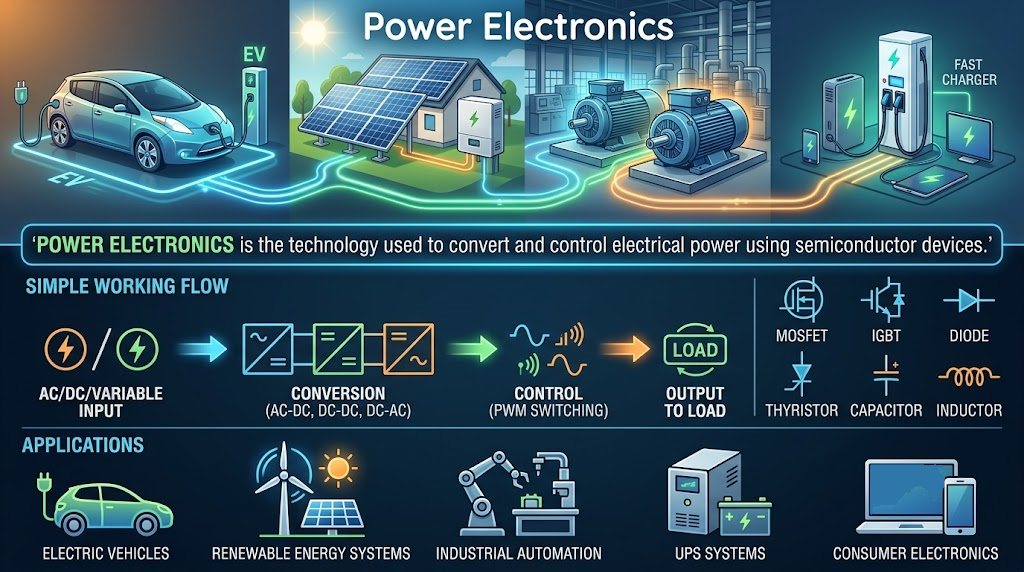
Your charger, solar inverter, and variable-speed motor drive all change how electrical energy reaches a load. The circuits doing that work are managing power, not just information.
Power electronics uses semiconductor devices and control circuits to convert and regulate electrical energy. It can change voltage, current, frequency, or the form of a supply. Efficiency matters because even a small percentage of lost power can create substantial heat.
How power electronics works
Many converters switch semiconductor devices rapidly between conducting and blocking states. Inductors, capacitors, and sometimes transformers store or transfer energy as the switching sequence changes.
A controller adjusts the sequence to meet an output target. Feedback can compensate for changing input voltage or load, provided the design remains within its limits.
- Measure an output quantity such as voltage or current.
- Compare the measurement with the reference.
- Calculate an appropriate control action.
- Drive the power switches with the required timing.
- Transfer energy through the power stage.
- Monitor limits and respond to faults.
Not every power electronics circuit uses high-frequency PWM. Controlled rectifiers, phase-control circuits, and linear approaches have different behavior and trade-offs.
Four common converter types
| Conversion | Typical circuit | Example application |
|---|---|---|
| AC to DC | Rectifier, often followed by filtering and regulation | A DC power supply |
| DC to DC | Buck, boost, or another converter | Battery voltage regulation |
| DC to AC | Inverter | Motor drives and backup power |
| AC to AC | AC controller or frequency-conversion system | Suitable heating and speed-control systems |
A complete product may contain several stages. A motor drive, for example, can rectify its AC input, store energy on a DC link, and use an inverter to supply the motor.
Devices used in power electronics
- Diodes: rectification and current paths during switching.
- MOSFETs: controlled switches used across many power levels.
- IGBTs: useful in many higher-voltage power stages.
- Thyristors: controlled conduction in suitable power-control circuits.
- Gate drivers: provide the voltage and current pulses needed by switches.
Silicon, silicon carbide, and gallium nitride devices offer different characteristics. Don’t choose by material alone: voltage, switching frequency, losses, cost, and drive requirements all matter.
Why the gate driver matters
A controller output often can’t drive a power switch directly. Gate charge, isolation, level shifting, and protection can require a dedicated driver.
In a half-bridge, incorrect timing can turn both switches on together and short the supply. Dead time and protection must be designed around the actual devices and circuit.
A buck converter example
An ideal buck converter in continuous-conduction steady state has the approximate relationship Vout = D × Vin, where D is duty cycle.
With 12 V input and a duty cycle of 0.5, that model predicts 6 V output. Real output depends on device drops, losses, load, operating mode, and the control system.
This power electronics example isn’t a complete design. You must also select inductance, capacitance, current limits, switching frequency, layout, and protection.
Where does the lost power go?
Conduction loss occurs while current flows through nonzero resistance or voltage drops. Switching loss occurs during transitions, when significant voltage and current can overlap.
Magnetics, capacitors, drivers, and control circuitry add losses too. Layout inductance can cause voltage overshoot, while fast switching can increase electromagnetic interference.
If a converter delivers 90 W at 90% efficiency, input power is 90/0.9 = 100 W. The remaining 10 W becomes losses under those conditions.
What to check in a real system
- Input range, output requirements, and startup behavior.
- Continuous and peak current, including faults.
- Voltage stress and switching transients.
- Thermal design, isolation, and protection requirements.
- Ripple, noise, stability, and electromagnetic compatibility.
Power electronics can involve lethal voltage and stored energy. Learn switching behavior with simulation or an appropriately protected low-voltage educational module, not an exposed mains converter.
Follow the energy path
Power electronics becomes easier to understand when you trace energy from the source, through switches and storage components, to the load.
Start with a buck-converter simulation. Change duty cycle and load, then compare output voltage, inductor current, and losses with the ideal relationship.
Comments
Comments are currently closed.