
What Is an Induction Motor? Working and Types
A motor can turn a pump all day even though no wire feeds electricity directly into its spinning rotor. How does the rotor get the current it needs?
An induction motor is an AC motor whose stator magnetic field induces current in the rotor. That current interacts with the field and produces torque. You’ll find this design in equipment ranging from household fans to factory conveyors.
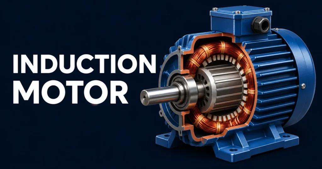
Main parts of an induction motor
The easiest way to picture the motor is to start at the shaft and work outward. The shaft passes through the rotor, the rotor sits inside the stator, and the housing holds the assembly together. A narrow air gap lets the rotor turn without touching the stator.
- Stator. The stationary part holds insulated windings in slots around a laminated steel core. AC in the windings creates a magnetic field across the air gap.
- Rotor. The rotating part contains conductive bars or insulated windings. These provide a path for induced current. The rotor turns with the shaft.
- Bearings and housing. The bearings support the shaft and keep it centred. The housing protects the assembly and helps dissipate heat. Many designs also have a cooling fan.
Both magnetic cores are typically made from thin steel laminations. The layers limit unwanted circulating currents in the core, called eddy currents, which would otherwise waste more energy as heat. The rotor conductors, by contrast, are deliberately arranged to carry useful induced current.
How does an induction motor work?
Start with a three-phase induction motor. Its windings are placed around the stator, and their currents rise and fall at different times. Add those fields together and you get a magnetic field that sweeps around the air gap. The stator itself stays still.
- The supply creates a rotating field. The three AC phases are offset by 120 electrical degrees. With the windings arranged around the stator, this timing sets the field moving in a definite direction.
- The moving field induces rotor voltage. At startup the rotor is stationary, so the field moves past its conductors. The changing magnetic flux induces a voltage by electromagnetic induction.
- Rotor current produces torque. Because the rotor conductors form closed paths, current flows. Its interaction with the stator field exerts force on the rotor conductors and turns the shaft in the direction of the field.
- The rotor settles at a working speed. As it speeds up, the difference between rotor speed and field speed falls. At steady speed, the motor’s torque balances the load torque and mechanical losses.
The induction step resembles what happens in a transformer. A changing magnetic field transfers energy from one circuit to another. In a motor, the magnetic interaction also produces torque, so part of the input power leaves through the shaft as mechanical power.
When you add load, the rotor slows a little. The field then moves faster relative to the rotor. In the normal running range, this increases rotor current and torque until the motor reaches a new balance. A load beyond the motor’s torque capability can cause it to stall.
Synchronous speed and slip
Synchronous speed is how fast the stator field rotates. It depends on supply frequency and the number of magnetic poles built into the winding. For an induction motor, the shaft speed during normal motoring is slightly lower. Engineers call the difference slip.
Synchronous speed: Ns = 120 × f ÷ P
Here, Ns is in revolutions per minute (rpm), f is the electrical frequency in hertz, and P is the total number of poles. At 50 Hz, a two-pole field rotates at 3,000 rpm, a four-pole field at 1,500 rpm, and a six-pole field at 1,000 rpm.
Percentage slip: (Ns − Nr) ÷ Ns × 100, where Nr is the rotor speed.
Example with a four-pole motor
Say a four-pole induction motor runs at 1,440 rpm at rated load on a 50 Hz supply. The field turns at 1,500 rpm. Subtract 1,440 from 1,500 and you get 60 rpm of slip speed. Divide 60 by 1,500 and multiply by 100 to get 4% slip.
Why can’t the shaft keep up with the field? At synchronous speed, the fundamental stator field would be stationary relative to the rotor. That field would induce no rotor voltage and produce no sustained induction torque. Even an unloaded motor needs a little slip to overcome bearing friction and air drag.
At startup, shaft speed is zero, so slip is 100%. In the 4% example, the rotor current frequency is just 0.04 × 50, or 2 Hz. That’s the frequency seen by the rotor conductors as the field passes them, even though the stator still receives a 50 Hz supply.
Types of induction motors
You’ll see two kinds of descriptions on spec sheets. Single-phase and three-phase tell you about the AC supply. Squirrel-cage and wound-rotor tell you about the rotor construction. A three-phase squirrel-cage induction motor is one common combination.
| Feature | Single-phase | Three-phase |
|---|---|---|
| Supply | Single-phase AC | Three-phase AC |
| Starting field | Needs a starting arrangement, such as an auxiliary winding and capacitor | Three stator phases inherently create a rotating field |
| Typical rotor | Squirrel cage | Usually squirrel cage, sometimes wound rotor |
| Example loads | Small fans, pumps and compressors | Industrial pumps, blowers, conveyors and machine tools |
Single-phase induction motor
A single main winding produces a pulsating field. At standstill, that field alone produces no net starting torque. One common solution is an auxiliary winding placed apart from the main winding. A capacitor can shift the timing of current in the auxiliary winding, giving the rotor a definite direction at startup.
A capacitor-start design typically disconnects its start circuit once the motor accelerates. A permanent split capacitor motor keeps its run capacitor in circuit. Shaded-pole designs use a shorted copper loop to create a weak starting field and suit small loads such as some fans.
Three-phase induction motor
A balanced three-phase supply produces a rotating stator field directly, so the motor has starting torque without a separate starting winding. It still needs controls and protection suited to the motor, load and supply. A loaded conveyor, for example, can require more starting torque than a fan that starts from rest.
Squirrel-cage and wound-rotor designs
A squirrel-cage rotor uses conductive bars joined by end rings. Picture a cylinder with bars running between two rings. These closed paths carry induced current, and there are no rotor brushes or slip rings to service. That simple construction is one reason the squirrel-cage induction motor is widely used.
A wound-rotor induction motor uses insulated rotor windings connected to slip rings. External resistance can be inserted during startup to shape the torque and limit current. This can help with some heavy starting loads, although the rings and brushes add maintenance.
Starting current and speed control
An induction motor started directly across the line can briefly draw several times its rated running current. The size of that surge depends on the design. Whether it matters depends on the supply and what the shaft is driving.
- Direct-on-line starter. Applies full line voltage at startup. It’s simple and can suit loads and supplies that tolerate the current surge and mechanical shock.
- Soft starter. Ramps the applied voltage during startup to reduce current and soften acceleration. Lower voltage also reduces available starting torque, so the load still has to be able to accelerate.
- Variable frequency drive (VFD). Changes the frequency and controls the voltage supplied to a compatible motor. Changing frequency changes synchronous speed, so the drive can control running speed as well as acceleration.
Imagine a ventilation fan that only needs full airflow during part of the day. A VFD lets the fan run slower when demand drops. A soft starter can smooth the same fan’s startup, but once it reaches line operation it doesn’t provide continuous speed adjustment.
Cooling matters if you plan to run an induction motor slowly for long periods. A shaft-mounted fan also slows down as the motor slows. Some applications use separately powered ventilation or a motor rated for the required speed range and duty.
Applications and how to choose a motor
Look for an induction motor wherever equipment needs reliable rotary motion. Centrifugal pumps and ventilation fans are familiar examples. Factories also use these motors on mixers, conveyors and machine tools. The type you choose depends on the job the shaft has to do.
- Supply. Check the available voltage, phase and frequency against the nameplate.
- Load. Consider the torque needed at startup and during normal running. A conveyor that starts while loaded can be harder to accelerate than a centrifugal fan.
- Speed and duty. Check whether the load needs a steady speed or a range of speeds, and whether the motor will run continuously or start and stop frequently.
- Environment. Match the enclosure and cooling design to the expected dust, moisture and temperature.
Rated power tells you how much mechanical output the motor can deliver at its rated conditions. It doesn’t tell you the starting torque or the exact running speed. Two motors with the same power rating can have different pole counts, so check rated rpm and torque data before treating them as interchangeable.
Comments
Comments are currently closed.