
What Is a Breadboard? How to Build a Circuit Without Soldering
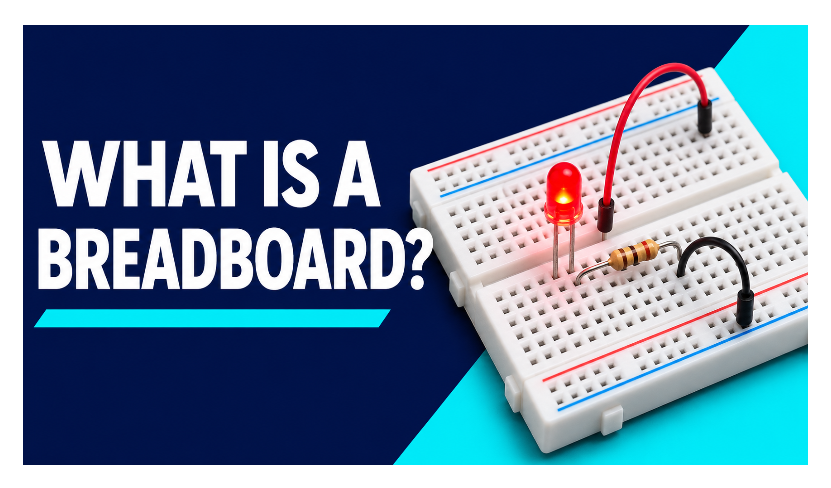
Want to see an LED light up before you solder a single wire? With a breadboard, you can build the circuit, move a connection, and try again in minutes.
A breadboard is a reusable board that connects electronic components without soldering. Hidden metal clips join groups of holes. Once you know which holes share a connection, you can use the board to test everything from a simple LED to a small sensor circuit.
How a breadboard works
Look closely at the top of a solderless board. You’ll see rows of holes, usually with letters across the top and numbers down the side. Beneath those holes, spring contacts grip component leads and jumper wires. Each strip of contacts is one piece of metal, so the holes above it share an electrical connection.
Think of a connected group as a junction on a circuit diagram. If you plug a resistor lead and a jumper wire into two holes in that group, they meet at the same junction. Move the jumper into a different group and you’ve changed the circuit, even if the new hole sits right beside the old one.
That’s what makes the board useful for prototyping. You can test an idea before you decide where to solder the parts. If an LED is dim, you can swap the resistor. If a switch is wired to the wrong point, you can pull out one jumper and move it. You can also reuse the parts when the experiment is over.
Which breadboard holes are connected?
Terminal strips and the center gap
On a typical full-size breadboard, each numbered row has two groups of five connected holes. A10 through E10 form one group, and F10 through J10 form another. E10 and F10 sit across the center gap and are electrically separate. A10 and A11 belong to different rows and are separate as well.
That center gap is handy for a dual in-line integrated circuit, or DIP chip. Its two lines of pins can straddle the gap. Each pin then has its own group of holes for jumpers, so you can reach the pins without joining the two sides of the chip together.
Power rails and split rails
The long strips near the edges are called power rails. You can connect the positive supply to the rail marked plus and the supply return to the rail marked minus. The colored lines tell you how the rails are labeled. You still have to connect your power source before they carry voltage.
- Some rails run the full length of the board. Others have a break near the middle.
- The rails on opposite sides usually need separate jumper wires if you want them to share power.
- Mini boards sometimes have only terminal strips. You can use an available group as a local junction for power or return.
When in doubt, check the board with a multimeter in continuity mode. Disconnect the battery or supply first. On an empty board, insert a jumper into each hole you want to test and touch a probe to each jumper’s exposed end. A beep usually means the holes share a connection. Try this on two holes along the same rail, including a pair that spans the middle.
Build a simple LED circuit on a breadboard
Start with a red LED, a 330 Ω resistor, a holder for three AA alkaline cells, and a few jumper wires. The battery pack supplies about 4.5 V nominally. A standard quarter-watt resistor is suitable for this example. If you’re using loose battery holder leads, make sure their ends connect securely to the board without stray strands touching nearby contacts.
The idea is to make one path from battery positive through the resistor and LED and back to battery negative. You can use the following hole labels on a board with the common A–J layout, or choose any three separate terminal groups.
- Disconnect the battery pack. Leave at least one supply lead off the board while you place the parts.
- Place the LED. Put its anode in E10 and its cathode in E12. On a new through-hole LED, the longer lead usually identifies the anode. The flat edge on the body usually marks the cathode. If the leads were trimmed and you’re unsure, check the part’s datasheet.
- Add the resistor. Insert one lead in C10, which connects it to the LED anode. Place the other lead in C8. A standard resistor has no polarity, so either lead can go in C10.
- Connect the supply return. Put the battery holder’s negative lead in A12 so it shares a connection with the LED cathode.
- Check your wiring and connect power. Confirm that the resistor bridges rows 8 and 10 and the LED bridges rows 10 and 12. Then connect the battery holder’s positive lead to A8. The LED should light.
Why the LED needs a resistor
The resistor limits the current through the LED. Once a forward-biased LED starts conducting, a small increase in voltage can produce a large increase in current. The series resistor makes the current easier to control and helps protect the LED.
Estimate the current by subtracting the LED’s forward voltage from the supply voltage and dividing by the resistance. With a nominal 4.5 V supply and an assumed 2.0 V drop across the LED, the calculation is (4.5 V − 2.0 V) ÷ 330 Ω ≈ 7.6 mA. Your reading can differ because the battery voltage and the LED’s forward voltage vary.
The resistor can sit on either side of the LED as long as both parts stay in the same series path. If you draw the circuit on paper, trace the line from positive to negative. Every route through the LED should pass through the resistor.
Test and troubleshoot your breadboard circuit
If the LED stays dark, start with the connections you can see. Look at where each lead actually enters the board. It’s easy to count the wrong row or cross the center gap when you meant to share a connection.
- Check LED orientation. Disconnect the battery and confirm the anode faces the positive side of the circuit through the resistor.
- Check the groups. If both LED legs share a group, they sit at the same voltage. Move one leg to a separate group and check the connections again.
- Check any rails you used. If part of the circuit is powered and part is dead, look for a split rail or an unconnected rail on the other side.
- Check the contacts. A jumper that feels loose may make intermittent contact. With power off, reseat it in another hole in the same group.
Use a multimeter to narrow down the problem
To check the battery pack, set the meter to DC voltage. Put the black probe on battery negative and the red probe on battery positive. Then check for the same voltage between the board groups where the two battery leads connect. If the pack reads normally but the voltage is missing at the board, check the leads and their contacts.
Once the LED lights, measure the voltage across the resistor and divide by its resistance to estimate the current. You can make that measurement with the circuit running and the meter set to DC voltage. If you need to check continuity again, disconnect the battery first. Other components can create additional paths on an assembled board, so isolate the connection if the result is unclear.
Breadboard vs perfboard vs PCB
| Board type | How parts connect | When to use it |
|---|---|---|
| Solderless breadboard | Spring contacts join selected holes | Learning, experimenting, and changing a design quickly |
| Perfboard with isolated pads | Parts are soldered to individual pads and wired together | Making a one-off circuit you want to keep assembled |
| Custom printed circuit board (PCB) | Designed copper traces connect soldered parts | Making compact or repeatable builds |
A solderless board is a good fit when your circuit is still changing. If you’re turning it into a device that will travel in a bag or sit inside a vibrating enclosure, soldered connections are more secure. Perfboard gives you room to assemble a one-off by hand. A custom PCB makes it easier to reproduce the same wiring on multiple copies.
Where a solderless board has limits
Use a breadboard for low-voltage, low-current experiments. Keep mains voltage off it and check the board manufacturer’s ratings before connecting loads that draw more current. A motor, heater, or other heavy load can call for wiring and connectors designed for the job.
Fast signals can also be sensitive to the layout. Long jumper wires and nearby contacts introduce small unwanted electrical effects, including stray capacitance and inductance. Short wires can help with a simple prototype. A circuit that depends on very fast edges or sensitive measurements may need a different layout and more controlled connections.
What to try next
Build the LED circuit, then disconnect the battery and move the positive jumper from A8 to another hole in the same connected group. Reconnect the battery. The LED should still light because the electrical connection is the same.
Once you can predict what will happen when you move a wire, try adding a push button in series. Use the continuity setting to identify which button pins connect when you press it. Then wire the button into the path and see whether the LED responds the way your drawing predicts.


Comments
Comments are currently closed.