
What Is a Microcontroller? Architecture, Working and Uses
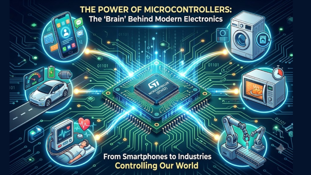
A tiny chip can read a temperature sensor, update a display, and decide when a fan should run. That chip may cost less than the parts it controls.
A microcontroller combines a processor, memory, and useful input/output hardware in one integrated circuit. You give it a program, and it repeatedly reads inputs and controls outputs. Here’s what happens inside and how you can choose one for a project.
What’s inside a microcontroller?
Most devices bring several building blocks together. Their exact mix depends on the part number, so a family name alone doesn’t tell you what’s available.
- CPU: executes instructions and performs calculations.
- Program memory: commonly Flash, which retains firmware when power is removed.
- RAM: holds working data while the device runs.
- GPIO: digital pins that read or produce logic signals.
- Timers: measure intervals, count events, or generate pulses.
- Peripherals: may include ADCs, communication interfaces, watchdogs, and security hardware.
Memory and peripherals do different jobs
Flash stores your program; RAM stores changing values such as sensor readings and buffers. Some devices also provide EEPROM or other nonvolatile storage for settings.
An ADC converts an analog input into a numeric code. PWM hardware changes a pulse train’s duty cycle. PWM isn’t a true analog voltage output, although a suitable filter can turn it into an approximate one.
How does a microcontroller work?
Imagine a low-voltage temperature indicator. Its firmware compares a reading with a limit and switches an LED on when the limit is exceeded.
- Power and reset bring the chip into a defined starting state.
- Startup code prepares memory, clocks, pins, and peripherals.
- The program reads the sensor through an ADC or digital interface.
- The CPU processes the reading and chooses an action.
- An output changes, then the program repeats or waits for an event.
A microcontroller doesn’t need to keep checking every input continuously. Interrupts let selected events request attention, while timers and DMA can handle work with less CPU involvement.
Firmware, interrupts, and an RTOS
Simple firmware may use one repeating loop. A more demanding application may use a real-time operating system to organize tasks and deadlines.
Neither approach guarantees correct timing by itself. You still need to check the worst-case execution time, interrupt delays, shared data, and what happens when a sensor fails.
Microcontroller vs microprocessor
| Feature | Typical MCU | Typical application MPU |
|---|---|---|
| Memory | Useful program memory and RAM often on chip | Often uses external main memory |
| Main role | Control and sensing | More demanding software and interfaces |
| Software | Main loop, RTOS, or another supported environment | Often a rich operating system |
| Board needs | Often relatively compact | May need more support circuitry |
These are tendencies, not rigid rules. Modern chips blur the boundary, and both families can contain multiple cores, caches, and many peripherals.
A simple timing example
Suppose a timer receives a 1 MHz clock after its prescaler. One timer tick lasts 1 microsecond. An interval of 1,000 ticks therefore lasts 1 millisecond.
That doesn’t mean you should blindly write 1,000 to a register. Many counters include zero in their count, and register formulas differ. Use the device’s timer chapter to translate the required interval into its actual settings.
The CPU clock also isn’t the same as useful work per second. Instruction execution, memory access, peripheral clocks, and software structure all affect performance.
How to choose and connect your chip
- List the required pins, communication interfaces, and analog channels.
- Estimate firmware storage and working RAM, including buffers.
- Check supply voltage, input limits, and output current ratings.
- Compare sleep modes and total system power.
- Check tools, debugging support, availability, and documentation.
Don’t drive a motor or relay directly from an ordinary GPIO pin. Use a suitable driver and protection for inductive loads. An LED normally needs current limiting, and a 5 V sensor output may need level shifting before reaching a 3.3 V input.
Start with one input and one output
A microcontroller becomes easier to understand when you connect each hardware block to a real task. Pins sense the outside world, firmware makes decisions, and peripherals handle much of the timing.
Start with a button and a current-limited LED on a development board. Read the pin specifications, write a small program, then add a timer instead of relying on a long blocking delay.

Comments
Comments are currently closed.