
What Is a Transistor? Working, Types and Uses
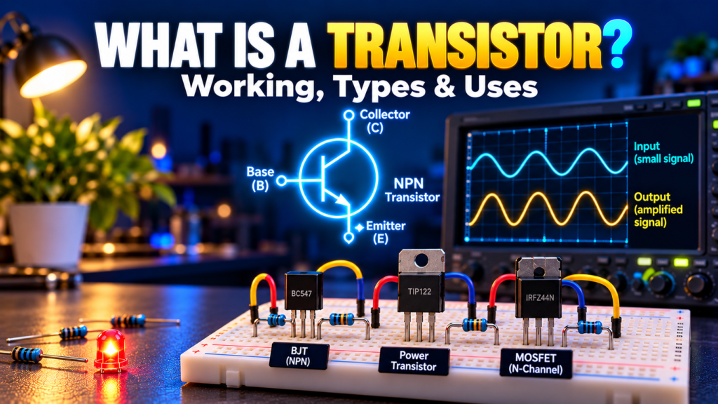
How can a tiny component turn a weak sensor signal into an action, or switch a motor on and off? A transistor makes both possible.
A transistor is a semiconductor device that controls current using an electrical signal. It can act as a switch or an amplifier, and billions of very small transistors can fit inside a modern integrated circuit. This guide explains the basics without assuming you already know semiconductor physics.
Contents
- What a transistor does
- Semiconductors and terminals
- How a BJT works
- How a MOSFET works
- BJT vs MOSFET
- Using a transistor as a switch
- Using a transistor as an amplifier
- Choosing and testing a transistor
- Applications and common questions
What is a transistor?
A transistor is an electronic component that uses a signal at one terminal to control current through other terminals. That control lets a small signal influence a larger one. The extra energy in an amplified output comes from the circuit’s power supply, not from the transistor creating energy.
Think of the transistor in a battery-powered fan controller. A microcontroller pin can send a control signal, but the fan may need more current than the pin can safely deliver. A correctly chosen transistor can switch the fan’s supply current while the microcontroller controls it.
Transistors are made in many sizes and packages. Some are discrete parts with three visible leads. Others are microscopic structures inside chips. Their common job is control, although the details depend on the device type and circuit.
Why semiconductors matter
Silicon is a semiconductor: its electrical behavior can be modified by adding tiny amounts of selected impurities, a process called doping. N-type material has electrons as its majority carriers; P-type material has holes as its majority carriers. A hole describes a missing electron that behaves like a positive charge carrier.
Arrangements of these materials create junctions and electric fields that let designers control current. You don’t need to follow every carrier to use a transistor, but recognizing the terminals and their voltage limits is essential.
Two common families are bipolar junction transistors (BJTs) and field-effect transistors (FETs). A common FET is the MOSFET. They perform similar circuit roles but respond differently to their control signals.
How does a BJT transistor work?
A BJT has three terminals: base, collector, and emitter. Its two basic polarities are NPN and PNP. The directions of voltages and conventional current are reversed between them, so a circuit designed for one can’t automatically use the other.
For a typical silicon NPN transistor in a suitable circuit, a forward-biased base–emitter junction allows base current to flow. In the active region, the collector current is approximately related to base current by IC ≈ β × IB, where β is the DC current gain. This is a useful approximation, not a fixed value to rely on for every device, current, or temperature.
The base–emitter voltage is often around 0.6–0.8 V when conducting, but it varies with current, temperature, and the device. Always use the datasheet for a real design.
Cutoff, active region, and saturation
- Cutoff: the transistor is mostly off, apart from leakage current.
- Forward-active: the collector current responds to the input; this region is commonly used for linear amplification.
- Saturation: both junctions are forward biased and the transistor behaves as a switched-on device with a nonzero collector–emitter voltage.
For a switch, designers deliberately provide enough base drive to reach saturation at the intended load current. A base resistor limits current from the control source. Don’t assume that the maximum gain listed in a datasheet guarantees a saturated switch.
How does a MOSFET transistor work?
A MOSFET usually has a gate, drain, and source. A voltage between gate and source controls a conducting channel. In an enhancement-mode N-channel MOSFET, a sufficiently positive gate-to-source voltage creates a channel that allows current between drain and source.
The gate is insulated, so it draws very little steady-state current under normal conditions. However, the gate behaves capacitively: current is needed to charge and discharge it when switching. Fast switching or a large MOSFET may therefore require a gate driver.
A datasheet’s gate threshold voltage is the point at which a small specified drain current begins to flow. It does not mean the MOSFET is fully on at that voltage. Check the on-resistance, RDS(on), specified at the actual gate-to-source voltage your circuit can provide.
Power MOSFETs also have an intrinsic body diode. Its direction and effect matter in reverse-voltage and switching circuits. Check the datasheet rather than treating the device as an ideal switch in both directions.
BJT vs MOSFET: a simple comparison
| Feature | BJT | MOSFET |
|---|---|---|
| Control terminals | Base and emitter | Gate and source |
| Input behavior | Needs base current in normal operation | Gate voltage controls channel; gate charge matters during switching |
| Typical switch loss | Approximately VCE(sat) × load current | Approximately I² × RDS(on) while on |
| Common uses | Small switches, amplification, current sources | Power switches, motor drives, digital ICs |
Neither device is automatically best for every job. A small BJT may be inexpensive and easy to use for a modest load. A logic-level MOSFET can be a good choice for a higher-current low-voltage switch when its ratings and gate drive are suitable. For a deeper comparison, see MOSFET vs BJT.
Example: using an NPN transistor as a switch
Imagine a 5 V supply powering a small indicator load that draws about 20 mA. A microcontroller output controls an NPN transistor used as a low-side switch: the load connects between +5 V and the collector, while the emitter connects to ground. The microcontroller and load supply must share the appropriate ground reference.
- Choose a transistor with collector current and voltage ratings comfortably above the load’s requirements.
- Connect a resistor between the controller output and the base. Check the transistor pinout: packages that look alike can have different pin arrangements.
- When the output drives the base appropriately, the transistor switches on and current flows through the load.
- When the output goes low, base drive stops and the load switches off.
As a starting calculation, suppose the control output is 5 V, the assumed base–emitter voltage is 0.7 V, and the target base current is 2 mA. The resistor is approximately R = (5 − 0.7) / 0.002 = 2,150 Ω. A nearby standard value such as 2.2 kΩ gives about 1.95 mA under those assumptions. Check the output pin’s current capability and the transistor’s saturation specifications before using the design.
If the load is a relay coil or motor, add a suitable flyback diode across the load, oriented so it is reverse-biased during normal operation. It provides a path for inductive current when the switch opens. The diode’s current and voltage ratings must suit the load. An LED load also needs its own current-limiting resistor.
How can a transistor amplify a signal?
A transistor amplifier uses a power supply and a carefully chosen operating point, called its bias. A small change at the input controls a larger change in output current or voltage. A resistor or another load converts a current change into a voltage change.
For example, a common-emitter BJT stage can amplify a small alternating signal. Its output voltage is typically inverted relative to the input. Capacitors may couple the signal between stages while blocking unwanted DC, and bias resistors keep the transistor in a useful operating region.
Amplification has limits. If the signal pushes the device outside its intended region, the output can clip and distort. Noise, temperature, frequency response, and available supply voltage also affect the result. A transistor doesn’t provide unlimited gain simply because it is connected to a battery.
How to choose a transistor
Start with the job: switch or amplifier, supply voltage, load current, and speed. Then compare these requirements with the manufacturer’s datasheet. Pay attention to the following:
- Voltage rating: leave margin for supply changes and switching transients.
- Current rating: consider continuous and peak currents, as well as the device’s safe operating area.
- Drive: ensure the control circuit can supply the required BJT base current or MOSFET gate voltage and charge.
- Power and heat: estimate conduction and switching losses. Ratings depend on cooling and temperature.
- Package and pinout: confirm physical fit and terminal order before wiring.
- Frequency: check switching times or amplifier frequency response where speed matters.
For a MOSFET carrying 1 A with an on-resistance of 0.1 Ω at the available gate voltage, approximate on-state conduction loss is I²R = 1² × 0.1 = 0.1 W. This ignores switching losses and temperature changes; it’s a starting estimate, not a complete thermal design.
How to test a transistor safely
Disconnect power and discharge relevant capacitors before testing. For a BJT removed from a circuit, a multimeter’s diode mode can often check its base–emitter and base–collector junctions. A good-looking diode reading doesn’t prove the transistor will work under load, and a circuit’s other components can make in-place readings misleading.
MOSFET testing requires more care because a charged gate can leave the device on. Follow the manufacturer’s guidance, avoid exceeding gate voltage limits, and use electrostatic precautions. If a part is suspect, compare measurements with its datasheet or test it in a controlled circuit.
Where are transistors used?
- Computers and phones: MOS transistors form logic, memory, and processing circuits.
- Audio: transistor stages amplify signals for speakers and headphones.
- Power supplies: switching transistors control energy conversion.
- Control systems: drivers switch relays, LEDs, and motors.
- Sensors: amplifier circuits condition small signals for measurement.
Frequently asked questions
Is a transistor the same as a switch?
It can act as a switch, but it can also work in a linear circuit as an amplifier or current-control element. Its behavior depends on the circuit and operating conditions.
Does a transistor create power?
No. It controls energy supplied by the circuit. In an amplifier, the power supply provides the additional output energy.
Can I connect a motor directly to a microcontroller pin?
Usually not: the motor’s current and inductive voltage spikes can exceed the pin’s limits. Use a properly rated driver or transistor, an appropriate supply, and inductive-load protection.
Are all three-pin transistors interchangeable?
No. Polarity, pinout, voltage and current ratings, gain, gate-drive requirements, and package differ. Check the exact part number and datasheet.
Once you understand how the control terminal affects the output path, transistor circuits become easier to read. Start with a low-voltage switch, check the ratings, and then explore amplification and more advanced drivers.


Comments
Comments are currently closed.