
What Are Logic Gates? Types and Truth Tables
Logic Gates Explained: Types, Truth Tables, and Examples
How does a computer make a decision using only electrical signals? It combines simple operations that answer questions like “Are both inputs on?” or “Is either input on?” Logic gates are the basic building blocks that perform those operations in digital circuits.
Once you understand a few truth tables, you can see how larger systems make decisions, store data, and calculate. This guide covers every basic gate, shows how to combine gates into useful circuits, and explains the real-world electrical limits that textbooks often skip.
Key takeaways
- A logic gate turns binary inputs (0 and 1) into an output using a fixed rule.
- The seven standard gates are AND, OR, NOT, NAND, NOR, XOR, and XNOR.
- NAND and NOR are “universal”: either can build any other gate.
- A truth table shows the ideal logic only. Voltage levels, timing, and loading decide whether real hardware works.
Topics covered
- What is a logic gate?
- Binary signals and truth tables
- Basic gates: AND, OR, NOT
- Derived gates: NAND, NOR, XOR, XNOR
- Logic gate truth table (all gates)
- How to build a simple logic circuit
- Half adder example
- Real-world considerations
- Applications of logic gates
- How to test a logic gate circuit
- FAQs
What Is a Logic Gate?
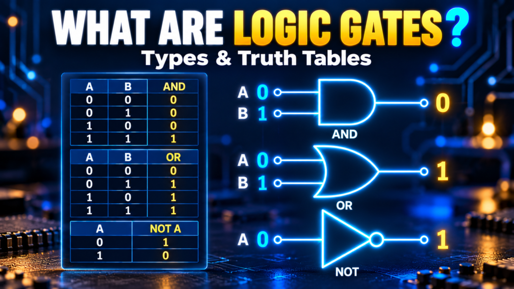
A logic gate is a digital circuit that produces an output according to a logical rule applied to its inputs. A two-input AND gate outputs logic 1 only when both inputs are 1. A NOT gate has one input and outputs the opposite value.
Digital logic represents two states as 0 and 1. In hardware, these correspond to voltage ranges set by the device, not necessarily exactly 0 V and 5 V. A gate must be powered and used within its electrical ratings to work reliably.
Gates are built from transistors and sold as individual integrated circuits (ICs). Millions or billions of them also sit inside microcontrollers, processors, and programmable logic devices. The simple rules stay useful even when the system is complex.
Binary Signals and Truth Tables
Binary uses two symbols, 0 and 1. Depending on the circuit, they can mean false and true, low and high, or inactive and active. Meaning depends on the design: an active-low reset, for example, is triggered when its signal is low.
A truth table lists every possible input combination and the resulting output.
- 1 input has 2 combinations
- 2 inputs have 4 combinations (00, 01, 10, 11)
- 3 inputs have 8 combinations
- In general, n inputs have 2ⁿ combinations
Truth tables describe logic behavior, not physical behavior. They don’t show propagation delay, power use, or whether a voltage is inside a chip’s allowed range. Those details come from the datasheet.
Basic Logic Gates: AND, OR, and NOT
AND Gate
An AND gate outputs 1 only when every input is 1. For inputs A and B: Y = A · B. The dot means logical AND, not a current measurement.
Example: a machine should run only when an enable switch is on and a cover sensor reports “closed.” That is AND logic. A real safety system, however, needs a safety-rated design, fault handling, and compliance with applicable standards. A simple gate alone is not enough.
OR Gate
An OR gate outputs 1 when at least one input is 1. Y = A + B, where the plus sign means logical OR, not addition.
Example: an indicator lights if either of two non-safety alarms is active. If both are active, the output is still 1. This is called inclusive OR.
NOT Gate (Inverter)
A NOT gate has one input and outputs the opposite: 0 becomes 1, and 1 becomes 0. Y = NOT A, often drawn with an overbar over A.
In schematics, a small circle (a “bubble”) on a gate’s input or output marks inversion. It does not indicate a power supply or a disconnected wire.
Derived Gates: NAND, NOR, XOR, and XNOR
NAND Gate
A NAND gate is an AND followed by inversion. Its output is 0 only when all inputs are 1. Y = NOT(A AND B).
NAND is a universal gate: any Boolean function can be built from NAND gates alone. For instance, tying both inputs together gives a NOT gate: Y = NOT(A AND A) = NOT A.
NOR Gate
A NOR gate is an OR followed by inversion. Its output is 1 only when all inputs are 0. NOR is also universal.
Universality is valuable in design and teaching, but it doesn’t mean a NAND-only or NOR-only circuit is always the most efficient. The best choice depends on available parts, speed, power, and constraints.
XOR Gate (Exclusive OR)
For two inputs, XOR outputs 1 when the inputs differ (01 or 10) and 0 when they match. It is used in adders, parity checks, and bit-difference detection.
With more than two inputs, a cascaded XOR gives 1 when an odd number of inputs are 1. That is not the same as “exactly one input is 1,” so always check the intended expression.
XNOR Gate
XNOR is the inverse of XOR. For two inputs, it outputs 1 when both inputs match (00 or 11). It works as a simple one-bit equality comparator.
Logic Gate Truth Table (Two-Input Gates)
| A | B | AND | OR | NAND | NOR | XOR | XNOR |
|---|---|---|---|---|---|---|---|
| 0 | 0 | 0 | 0 | 1 | 1 | 0 | 1 |
| 0 | 1 | 0 | 1 | 1 | 0 | 1 | 0 |
| 1 | 0 | 0 | 1 | 1 | 0 | 1 | 0 |
| 1 | 1 | 1 | 1 | 0 | 0 | 0 | 1 |
NOT gate (one input): input 0 gives output 1; input 1 gives output 0.
Use the table to check the expected output for every input combination before you move to hardware.
How to Build a Simple Logic Circuit
Suppose a lamp should turn on when the system is enabled and at least one of two sensors is active. Let E be enable, and A and B the sensors:
Y = E AND (A OR B)
- Feed A and B into an OR gate.
- Feed that result and E into an AND gate.
- If E = 0, Y is 0 whatever the sensors do. If E = 1 and either sensor is 1, Y is 1. If E = 1 and both sensors are 0, Y is 0.
This describes the logic only. A physical lamp or LED may need a transistor driver and a suitable supply, and an LED needs a current-limiting resistor. Sensor outputs must be compatible with the gate inputs and protected from out-of-range voltages.
Combining Gates: The Half Adder
A half adder adds two single bits using two gates:
- Sum = A XOR B
- Carry = A AND B
For A = 1 and B = 1, the sum is 0 and the carry is 1, which is binary 10. A half adder has no carry input from an earlier stage. A full adder adds that input, and chaining full adders builds multi-bit adders. This is how simple gate rules grow into arithmetic hardware.
Real-World Logic Gate Considerations
Logic Levels and Supply Voltage
Logic 0 and 1 are specified voltage ranges. One device’s guaranteed output must meet the next device’s input requirements, including noise margin. A 3.3 V output is not automatically a valid logic high for every 5 V input. Check VOH, VOL, VIH, and VIL in the datasheets, and use a level shifter when needed.
Floating Inputs
An unconnected input can pick up interference and produce an unpredictable state. Tie unused inputs to a valid level as the manufacturer instructs. Pull-up and pull-down resistors set a known default state while still letting a switch or another device change the signal.
Mechanical switches also bounce, producing several rapid transitions. Depending on the application, you may need hardware or software debouncing. A truth table doesn’t capture this time-dependent behavior.
Propagation Delay and Loading
Real gates take time to respond, and the delay varies with supply, temperature, load, and input edge. Signals on different paths can arrive at different times and cause a brief unwanted pulse called a glitch.
Outputs also have current and fan-out limits. A gate output may not safely drive a relay, motor, or high-current LED. Check output current, capacitive loading, and power dissipation, and add a driver where needed.
Power and Decoupling
Connect each IC’s supply and ground pins as specified, and place the recommended decoupling capacitors close to the supply pins to manage transient current and noise. Never exceed the chip’s permitted input range, including when the chip is unpowered.
Applications of Logic Gates
- Computing: arithmetic units, control circuits, and parts of processors
- Embedded systems: combining sensor and control signals
- Comparators: XOR and XNOR detect differences or equality between bits
- Communication: encoding, parity checks, and data handling
- Control: defined conditions for indicators and control signals
Gate circuits fall into two groups. Combinational circuits produce outputs that depend only on current inputs. Sequential circuits also depend on stored state, using latches or flip-flops, so timing and feedback matter much more.
How to Test a Logic Gate Circuit
- Identify the exact IC and confirm its supply range and pinout in the datasheet.
- Power it correctly and give every required input a valid high or low.
- Apply each truth-table combination and measure the output with a meter or logic probe.
- Confirm the measured voltages meet the next device’s input thresholds, not just that an LED looks on or off.
- If timing matters, use an oscilloscope or logic analyser to view transitions and propagation delay.
Use a safe low-voltage supply and switch power off before changing wiring. If the output is unexpected, check power, pin numbering, input levels, loading, and active-high versus active-low logic before assuming the IC is faulty.
Frequently Asked Questions
Are logic gates physical components or mathematical rules?
Both. Boolean logic defines the rule, and a physical gate implements it using transistors. Real hardware also has voltage and timing limits.
What is the difference between OR and XOR?
For two inputs, OR outputs 1 if either or both inputs are 1. XOR outputs 1 only when the inputs differ, so it outputs 0 when both are 1.
Why are NAND and NOR called universal gates?
Either type can be combined to build every other Boolean function. This is a logical property. Practical designs may still mix gate types.
Does logic 1 always mean 5 V?
No. Logic-high ranges depend on the device and supply. Many systems use 3.3 V or lower, so check the datasheet thresholds.
Can a logic gate drive a motor directly?
Usually not. A motor needs a suitable driver and protection against inductive voltage spikes. Check the load against the gate’s output ratings.
How many gates are in a processor?
Modern processors contain billions of transistors arranged into gates and larger structures, though the exact count varies by chip.
Conclusion
Logic gates turn binary inputs into decisions using simple, well-defined rules. Start with the truth table, translate the behavior into a Boolean expression, and build it from basic gates. Then check power, voltage levels, timing, and load requirements so the physical circuit is as reliable as the logic.



Comments
Comments are currently closed.