
What Is a Diode? Working, LED and Zener Explained
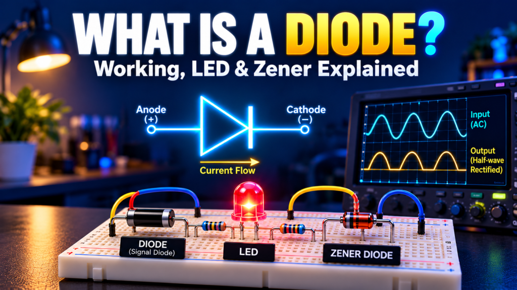
A small diode can protect a circuit from a backward battery or turn alternating current into a usable supply. Another diode can light up, while a Zener diode can help hold a voltage near a chosen value.
A diode is a semiconductor component that conducts more easily in one direction than the other. Understanding that one-way behavior—and its limits—makes it much easier to read electronic circuits. Let’s look at ordinary diodes, LEDs, and Zener diodes using practical examples.
Contents
- What a diode does
- How a diode works
- Symbols and polarity
- Common diode types
- How LEDs work
- How Zener diodes work
- Diode comparison
- Choosing and testing
- Common questions
What is a diode?
A diode is a two-terminal electronic component with an anode and a cathode. An ordinary semiconductor diode normally allows significant conventional current from anode to cathode when forward biased. It opposes current in the reverse direction, up to its reverse-voltage limits.
It isn’t a perfect one-way valve. A real diode has a forward voltage drop, some reverse leakage current, and a maximum reverse voltage. Too much current or heat can damage it. Special-purpose diodes are deliberately designed to use behaviors that would be unsuitable for an ordinary rectifier.
Diodes appear in power supplies, battery chargers, signal circuits, displays, and protection networks. One may be tiny and surface-mounted; another may be a large power device bolted to a heat sink. The symbol and datasheet reveal more than the package alone.
How does a diode work?
A common diode contains a junction between P-type and N-type semiconductor material. Near the junction, mobile charge carriers recombine and leave a region with relatively few mobile carriers, called the depletion region. An electric field develops across it.
When the anode is positive relative to the cathode, the diode is forward biased. The applied voltage reduces the junction barrier and current increases rapidly as voltage rises. A silicon diode is often approximated as having a 0.7 V forward drop, but the actual value changes with current, temperature, and the device.
When the cathode is positive relative to the anode, the diode is reverse biased. Only a small leakage current normally flows until breakdown is reached. Exceeding a standard diode’s reverse rating can cause damage, especially if the circuit doesn’t limit current.
Forward voltage isn’t a fixed threshold
Beginners often hear that a silicon diode “turns on at 0.7 V.” That’s a convenient approximation, not a sharp universal switch. A datasheet shows a current–voltage curve or forward-voltage limits at specified currents. Use those figures when the exact drop matters.
For example, if a diode drops 0.7 V while carrying 0.5 A, its approximate power dissipation is P = V × I = 0.7 × 0.5 = 0.35 W. The part must be able to dissipate that heat under the actual operating conditions. Reverse leakage and switching behavior also matter in some circuits.
Diode symbols and polarity
On a diode symbol, the bar marks the cathode. On many axial-leaded diodes, a painted band on the body marks that same terminal. Surface-mount packages and LEDs use different markings, so check the manufacturer’s documentation before connecting a part.
Conventional current flows from anode toward cathode when a standard diode is forward conducting. Electron flow is in the opposite direction. Circuit diagrams usually use conventional current; stay consistent when following a schematic.
Polarity matters during installation. A reversed rectifier may stop a circuit working, and a reversed LED may not light. Some LEDs have a flat edge or shorter lead near the cathode, but these clues aren’t reliable after leads have been cut or parts have been repackaged. Verify the exact device.
Common types of diode
Rectifier diode
A rectifier diode is designed to conduct current in one direction in a power circuit. A bridge rectifier uses four diodes to turn both halves of an AC waveform into pulsating DC. A capacitor can then reduce the ripple, and a regulator may provide a more stable output.
The output isn’t automatically perfect DC: diode drops, transformer regulation, load current, ripple, and capacitor ratings all influence the result. Never experiment directly with mains voltage on a breadboard. Use an appropriately isolated, low-voltage supply for beginner projects.
Schottky diode
A Schottky diode typically has a lower forward voltage drop than a comparable silicon PN diode and can switch quickly. That makes it useful in many low-voltage and switching-power circuits. Its reverse leakage can be higher, particularly as temperature rises, and suitable voltage ratings depend on the device.
Signal and switching diodes
Small-signal diodes handle relatively low currents and are useful for signal detection, clipping, and fast switching. They aren’t a substitute for a power rectifier simply because both conduct in one direction. Check peak current, average current, reverse voltage, and recovery characteristics.
What is an LED?
An LED, or light-emitting diode, produces light when forward current passes through its semiconductor junction. Electrons and holes recombine, releasing energy as photons. The semiconductor material and structure determine the color and other optical properties.
Different LEDs have different forward voltages. A red LED may have a lower forward voltage than a blue or white LED, but the actual range must come from its datasheet. Brightness depends on current and device characteristics; applying a voltage without controlling current can destroy the LED.
LED resistor example
Suppose you have a 5 V supply, a red LED with an assumed forward voltage of 2 V at the intended current, and a target current of 10 mA. The resistor estimate is:
R = (supply voltage − LED forward voltage) / LED current
R = (5 V − 2 V) / 0.010 A = 300 Ω. A standard 330 Ω resistor gives approximately (5 − 2) / 330 = 0.0091 A, or 9.1 mA under those assumptions. Its approximate dissipation is I²R ≈ 0.027 W. Choose a resistor with adequate power margin and verify the LED’s ratings and supply tolerance.
The LED and resistor must be in series so the same current flows through both. With multiple LEDs, plan each current path rather than assuming one resistor will share current evenly among parallel branches. For high-power LEDs, a suitable constant-current driver is usually a better choice than a simple resistor.
What is a Zener diode?
A Zener diode is designed to operate in reverse breakdown within specified current and power limits. In that region, its voltage changes relatively little as current varies. This makes it useful for simple voltage references, clamps, and basic shunt regulators.
In a basic shunt regulator, a series resistor connects a supply to the output node. The Zener connects from that node to ground with its cathode at the more positive node. The resistor limits current; the Zener conducts when the node voltage reaches its operating region.
A simple Zener calculation
Assume an idealized 12 V supply, a 5.1 V Zener, and a 1 kΩ series resistor. The resistor current is approximately (12 − 5.1) / 1,000 = 6.9 mA. If the load draws 2 mA, approximately 4.9 mA remains for the Zener. At that operating point its approximate dissipation is 5.1 × 0.0049 = 0.025 W.
This example doesn’t prove regulation under all conditions. Check minimum Zener current for the specified voltage, maximum current and power at the highest supply voltage and lightest load, resistor power, and temperature derating. If the load takes too much current, the Zener current falls below its useful range and output voltage drops. A dedicated voltage regulator is often a better choice for a variable or power-hungry load.
Rectifier diode vs LED vs Zener diode
| Type | Typical operation | Common purpose | Design check |
|---|---|---|---|
| Rectifier | Forward conduction, reverse blocking | AC-to-DC conversion | Current, reverse voltage and heat |
| LED | Forward conduction produces light | Indicators and illumination | Current limiting and forward voltage |
| Zener | Controlled reverse breakdown | Voltage reference or clamp | Current range and power dissipation |
All three have an anode and cathode, but they aren’t interchangeable. A rectifier may tolerate far more current than an indicator LED. A Zener’s reverse-breakdown behavior is selected for a purpose, while an ordinary diode’s reverse rating is generally a limit to stay below.
How to choose a diode
Start with the circuit’s voltage, current, and purpose. Then read the datasheet at the conditions you expect, including temperature. These checks cover many beginner projects:
- Forward current: consider continuous, peak, and surge current, not just a nominal load value.
- Reverse voltage: allow margin above the highest reverse voltage and expected transients.
- Forward voltage: check the drop at your actual current, especially in low-voltage circuits.
- Power and temperature: estimate dissipation and check the package’s thermal limits.
- Speed: recovery time and capacitance can matter in fast switching or high-frequency circuits.
- Package and polarity: match the footprint and confirm the cathode marking.
For an LED, also check color, brightness, viewing angle, and current. For a Zener, check its test current, tolerance, dynamic resistance, and power derating. A voltage printed in a product listing doesn’t describe the full operating range.
How to test a diode with a multimeter
- Disconnect power and safely discharge relevant capacitors. If you aren’t trained to work on a mains-powered device, leave it to a qualified technician.
- Select the meter’s diode-test mode. If possible, isolate at least one diode lead so other circuit paths don’t affect the reading.
- For a typical silicon diode, place the red probe on the anode and black probe on the cathode. The meter may show a forward voltage of several tenths of a volt.
- Reverse the probes. A healthy ordinary diode will usually show an open or over-range indication in this direction.
- Compare results with the meter and component documentation. An in-circuit reading or a diode-test reading alone doesn’t prove behavior at rated current or reverse voltage.
An LED may glow faintly during a diode test if the meter provides enough voltage. A standard multimeter’s diode mode usually cannot verify a Zener’s rated breakdown voltage; that requires a suitable current-limited test circuit and safe measurement practices.
Frequently asked questions
Can a diode block all reverse current?
No. Real diodes have reverse leakage, and reverse breakdown occurs if voltage is high enough. Stay within the device’s specified voltage, current, and temperature limits.
Does an LED need a resistor?
It needs current control. A series resistor is common for a simple fixed-voltage circuit; a constant-current driver may be more appropriate for high-power lighting or varying supply conditions.
Can a Zener diode replace any voltage regulator?
No. A simple Zener shunt circuit can be useful for small currents, but it wastes current and its output changes with load and device characteristics. A regulator IC may offer better efficiency, current capacity, or accuracy.
Why is a diode placed across a relay coil?
A flyback diode provides a path for the coil’s current when its switch turns off, limiting the voltage spike that could damage the switching transistor. It is normally reverse-biased while the coil is powered. Choose a diode rated for the application.
Once you can identify the anode and cathode, ask what the diode is doing in that particular circuit: rectifying, lighting, clamping, or protecting. Then check current, voltage, and heat before choosing a part.



Comments
Comments are currently closed.