
What Is Impedance and Reactance? Formulas and Examples
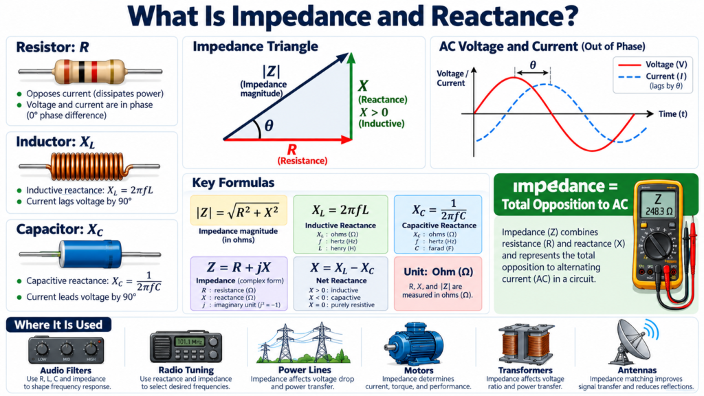
Impedance and reactance describe how circuit elements respond to alternating electrical signals. Impedance is the total opposition represented by the complex ratio of voltage phasor to current phasor. Reactance is the imaginary part of impedance and comes from energy storage in inductors and capacitors in the ideal models.
Resistance alone is enough for many introductory DC resistor problems. AC circuits need a fuller description because voltage and current can differ in phase as well as magnitude. This guide builds that description step by step, with formulas, a frequency comparison, and worked examples that connect complex notation to physical behavior.
Impedance and reactance: what is the difference?
Impedance is written Z = R + jX. The real part R is resistance, the imaginary part X is reactance, and j is the square root of minus one. Both R and X are measured in ohms, but they describe different relationships between voltage and current.
In an ideal resistor, electrical energy is dissipated as heat. An ideal inductor or capacitor stores energy temporarily and can return it to the circuit. Their contribution therefore includes a phase relationship rather than only a real voltage drop proportional to current at the same instant.
Reactance is part of impedance, not a competing total quantity. When a problem asks for total opposition in an AC network, it normally asks for impedance. When it asks specifically about the inductor or capacitor contribution, reactance is often the intended term.
| Quantity | Symbol | Physical role |
|---|---|---|
| Resistance | R | Real part; ideal resistor dissipates energy |
| Reactance | X | Imaginary part; phase and energy storage |
| Impedance | Z | Complex voltage-to-current ratio |
| Magnitude | Absolute Z | Ratio of consistent voltage and current magnitudes |
Inductive reactance formula
For an ideal inductor, Z_L = j omega L, where omega = 2 pi f. Its reactance is positive: X_L = 2 pi fL. Frequency f is in hertz, inductance L is in henries, and the result is in ohms.
An inductor of 0.1 H at 50 Hz has X_L = 2 pi times 50 times 0.1, approximately 31.4 ohms. At 100 Hz, its ideal reactance doubles to approximately 62.8 ohms. Increasing frequency makes the changing-current effect stronger.
This follows from the time-domain relationship v = L di/dt. For the same sinusoidal current amplitude, a higher frequency means a faster rate of current change and therefore a larger required voltage amplitude. In an ideal inductor, voltage leads current by 90 degrees.
Capacitive reactance formula
For an ideal capacitor, Z_C = 1/(j omega C), equivalent to minus j/(omega C). If X_C is used as a positive magnitude, X_C = 1/(2 pi fC), and the capacitor’s signed reactance is minus X_C.
For a 100 microfarad capacitor at 50 Hz, the reactance magnitude is about 31.8 ohms. At 100 Hz, it falls to about 15.9 ohms. Capacitive reactance decreases as frequency rises, opposite to the ideal inductor relationship.
The time-domain relationship is i = C dv/dt. For the same voltage amplitude, faster variation produces larger current. In an ideal capacitor, current leads voltage by 90 degrees. Keeping the sign convention clear is crucial when combining impedance and reactance values.
Combining impedance and reactance in series
For series elements, impedances add as complex quantities. A resistor, inductor, and capacitor in series have Z = R + j(X_L minus X_C), using positive magnitudes for X_L and X_C. The net reactance can therefore be positive, negative, or zero.
The magnitude is the square root of R squared plus (X_L minus X_C) squared. The phase angle is atan2(X_L minus X_C, R), with the appropriate quadrant. For positive resistance, a positive net reactance gives an inductive impedance angle.
Do not add resistance and reactance magnitudes arithmetically to get total magnitude. A 30 ohm resistor in series with 40 ohms of inductive reactance has magnitude 50 ohms, not 70 ohms. The quantities occupy perpendicular directions in the complex plane.
Worked example: a series RL circuit
A sinusoidal source of 100 V RMS supplies a series circuit with R = 30 ohms and X_L = 40 ohms. The impedance is 30 + j40 ohms, with magnitude 50 ohms and angle approximately 53.1 degrees.
RMS current magnitude is 100/50 = 2 A. Taking source voltage as the zero-angle reference, current has angle minus 53.1 degrees. It lags the source voltage, as expected for an inductive circuit.
The resistor voltage magnitude is 2 times 30 = 60 V, and the inductor voltage magnitude is 2 times 40 = 80 V. Their phasor sum has magnitude 100 V. Their ordinary numerical sum, 140 V, is not the source voltage because the two drops are 90 degrees apart.
Real power is I squared R = 4 times 30 = 120 W. Apparent power is 100 times 2 = 200 VA. The sinusoidal power factor is R divided by impedance magnitude, or 0.6 lagging. These results connect impedance and reactance directly to power calculations.
Worked example: net capacitive behavior
Take a series circuit with R = 20 ohms, X_L = 10 ohms, and X_C = 25 ohms. Net reactance is minus 15 ohms, so Z = 20 minus j15 ohms. Its magnitude is 25 ohms.
If the source is 50 V RMS, current magnitude is 2 A. The impedance angle is approximately minus 36.9 degrees, so current leads source voltage by approximately 36.9 degrees. The circuit behaves capacitively at this frequency even though it contains an inductor.
That last observation is important. The presence of an inductor does not guarantee an inductive total circuit. Compare the competing reactances at the actual operating frequency. At another frequency, the same RLC network could become resistive at resonance or inductive above it.
Impedance and reactance in parallel networks
Parallel branches share voltage, while their currents add as phasors. It is often easier to use admittance Y = 1/Z rather than trying to add impedance values directly. Admittance is measured in siemens and has real and imaginary parts.
For two parallel impedances, the equivalent is Z1 times Z2 divided by Z1 plus Z2, provided the complex operations are carried out correctly. The familiar two-resistor expression still works algebraically, but the quantities are now complex.
A useful practical warning follows: the series RLC magnitude formula is not a universal formula for all RLC arrangements. Parallel topology requires a different derivation. Draw the actual branches and apply KCL before simplifying.
Frequency, resonance, and real components
Impedance and reactance vary with frequency when energy-storage elements are present. In a simple series RLC circuit, inductive and capacitive reactances cancel at the ideal resonance frequency f0 = 1/(2 pi square root of LC). The remaining impedance is R.
This does not mean the inductor and capacitor individually have no voltage. Their voltages can be large and opposite in phase, while their sum cancels. Component ratings still matter, especially in a high-quality-factor circuit.
Real components add complications. An inductor has winding resistance, parasitic capacitance, and possible core losses. A capacitor has equivalent series resistance, leakage, and parasitic inductance. Ideal formulas are most useful within the components’ appropriate frequency and operating ranges.
A clear calculation method
- Confirm that sinusoidal steady-state analysis is appropriate.
- Convert frequency and component units correctly.
- Calculate angular frequency, omega = 2 pi f.
- Write each element’s complex impedance.
- Combine according to the actual series or parallel connections.
- Calculate phasor current and interpret magnitude and phase.
Use consistent RMS or peak quantities throughout a phasor calculation. Mixing an RMS voltage with a peak current creates incorrect power results. For power formulas, explicitly identify RMS values and the phase convention.
A calculator in degree mode can also produce confusion if an equation expects radians, or vice versa. Record the angle unit in the answer. Check the physical result: an inductive total impedance should make current lag, while a capacitive one should make it lead.
A useful limiting-case check
Consider what your ideal formulas predict as frequency approaches zero. Inductive reactance approaches zero, while capacitive reactance magnitude becomes very large. At very high frequency the trends reverse, within the ideal model. These limits help check the direction of a result, but real components eventually depart from ideal behavior because of parasitic effects. Use limiting cases to test the model algebra, then consult component data before extending the prediction across an unlimited frequency range.
Frequently asked questions
Are impedance and reactance measured in the same unit?
Yes, both use ohms. Impedance is complex and includes resistance plus signed reactance. Sharing a unit does not make the quantities identical, just as displacement components and total displacement can all use metres.
Can reactance be negative?
Yes. With the common engineering phasor convention, capacitive reactance is negative and inductive reactance is positive. Some textbooks use X_C for the positive capacitor magnitude, so inspect definitions before substituting values.
Does an ideal capacitor consume real power?
Its average real power over a steady sinusoidal cycle is zero. It stores and returns energy. A real capacitor can dissipate power because of nonideal losses, so practical behavior is not perfectly lossless.
Conclusion
Impedance and reactance extend circuit analysis beyond resistance by including phase and energy storage. Write Z = R + jX, track frequency and signs, and combine elements according to topology. Once the complex notation is connected to physical behavior, AC calculations become far more systematic.

Comments
Comments are currently closed.