
What Is an Op-Amp? Working, Circuits and Uses
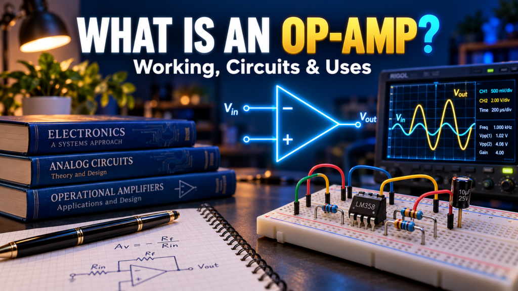
A sensor may produce only a tiny voltage, yet a controller needs a signal it can measure reliably. An op-amp can help bridge that gap.
An operational amplifier, or op-amp, is a high-gain differential amplifier used in circuits that amplify, filter, buffer, and process signals. With a few external components, the same device can perform several jobs. This guide explains how it works, what its formulas mean, and where real devices have limits.
Contents
- What is an op-amp?
- Inputs, output, and power
- Gain and negative feedback
- Common op-amp circuits
- Circuit comparison
- Real-world limitations
- Choosing an op-amp
- Testing and troubleshooting
- Frequently asked questions
What is an op-amp?
An op-amp is an integrated circuit that responds to the difference between two input voltages. Its output changes in a direction that depends on which input is at the higher voltage. The device usually has very high open-loop gain, meaning that even a small input difference can produce a large calculated output.
In practice, the output is limited by the supply and the device’s output capability. Most useful linear op-amp circuits therefore use negative feedback: part of the output is returned to the input in a way that opposes the input difference. External components then help set a predictable closed-loop response.
Op-amps are found in audio equipment, sensor interfaces, measurement instruments, active filters, and control systems. They don’t create energy; the power supply provides the energy delivered at the output.
The inputs, output, and supply pins
The two signal inputs are marked with plus and minus signs. The non-inverting input is marked +, and the inverting input is marked −. These labels describe the output’s response to a change at each input, not a requirement that one input must always have a positive voltage.
Holding the other input constant, a rise at the non-inverting input tends to make the output rise. A rise at the inverting input tends to make the output fall. The actual output depends on feedback, power supply, and operating limits.
An op-amp also needs supply connections. A dual supply might use +12 V, 0 V, and −12 V. A single-supply circuit might use 0 V and +5 V. The exact pins depend on the package: a chip can contain one, two, or four amplifiers. Always check its datasheet before wiring it.
What does differential input mean?
The input difference is Vdiff = V+ − V−. In a simplified open-loop model, Vout = AOL × Vdiff, where AOL is open-loop gain. This equation only describes linear behavior when the resulting output is within the device’s limits.
Both inputs also have a common-mode voltage relative to the supply. A real op-amp has an allowed common-mode input range. Even if the difference between the inputs is small, the circuit may fail to work correctly when both voltages lie outside that range.
How negative feedback controls gain
Imagine a non-inverting amplifier. The signal goes to the + input, while a resistor network feeds part of the output back to the − input. If the output rises too far, the feedback voltage rises too, reducing the input difference. The circuit settles where the feedback network and the input are approximately balanced.
For an ideal op-amp operating linearly with negative feedback, two useful approximations are: the input currents are nearly zero, and the two input voltages are nearly equal. These are analysis shortcuts, not physical laws. They don’t apply automatically when the output is saturated, the feedback is positive, or the input range is violated.
Feedback makes the closed-loop behavior depend heavily on external components. It can improve predictability, but it can’t remove every limitation. Finite bandwidth, output current limits, offset, and stability still matter.
Common op-amp circuits
Voltage follower
A voltage follower connects the output directly to the inverting input. The signal enters the non-inverting input, and the output approximately follows it: Vout ≈ Vin. Its voltage gain is approximately one.
Why use a circuit that doesn’t increase voltage? A follower can buffer a high-impedance source from a load. For example, a sensor’s output might change if connected directly to a measurement circuit. A suitable follower can reduce loading, provided its input range, output current, and stability are appropriate.
Non-inverting amplifier
In a standard non-inverting circuit, Rf connects output to the inverting input and Rg connects that input to the reference node. For an ideal amplifier with a ground reference:
Voltage gain = 1 + Rf / Rg
If Rf = 90 kΩ and Rg = 10 kΩ, the ideal gain is 10. A 0.2 V input would produce approximately 2.0 V, assuming the supply, input range, output swing, bandwidth, and load permit it. The output has the same signal polarity as the input.
On a single supply, the reference node may be a mid-supply voltage rather than ground. In that case, the formula applies to signal changes around that reference. Don’t assume the circuit can amplify a negative-going waveform below ground without an appropriate bias or negative supply.
Inverting amplifier
In a standard inverting circuit, the signal enters the − input through Rin, Rf connects output to that input, and the + input is connected to a reference. With an ideal op-amp and ground reference:
Voltage gain = −Rf / Rin
For Rf = 100 kΩ and Rin = 10 kΩ, gain is −10. A +0.2 V input ideally produces −2.0 V. The negative sign indicates inversion. This example needs a supply and output range that can reach the negative output; a 0–5 V single-supply circuit cannot produce −2 V relative to ground.
The inverting node is often called a virtual ground when the reference is ground and the circuit is operating linearly. Its voltage is near ground, but it isn’t a physical ground connection and cannot be treated as an unrestricted current return.
Other useful configurations
- Summing amplifier: combines input signals using resistors.
- Difference amplifier: responds to a voltage difference; resistor matching affects common-mode rejection.
- Active filter: combines an op-amp with resistors and capacitors to shape frequency response.
- Integrator: uses a capacitor in the feedback path to produce an output related to the integral of the input over a useful range.
These circuits need more than a formula. Component tolerances, bias currents, supply limits, and stability affect the result. A practical integrator, for instance, often needs a DC feedback path so offsets don’t drive its output into saturation.
Op-amp circuit comparison
| Configuration | Ideal voltage gain | Typical use |
|---|---|---|
| Follower | 1 | Buffering a signal |
| Non-inverting | 1 + Rf/Rg | Amplifying without inversion |
| Inverting | −Rf/Rin | Amplifying and inverting a signal |
| Comparator use | Not normally a linear-gain circuit | Indicating which input is higher |
A comparator is a device designed for comparing voltages and switching its output between states. Although some op-amps can be used for simple comparisons, a dedicated comparator is often a better choice because input range, recovery from saturation, output type, and speed differ. Check the datasheet; don’t assume every op-amp is suitable.
Real-world op-amp limitations
Input range and output swing
Input voltage must stay within the specified common-mode range. The output also cannot necessarily reach either supply rail. A “rail-to-rail” label needs context: it may refer to input, output, or both, and the actual limits depend on supply voltage and load.
For example, an op-amp powered from 0 V and 5 V cannot produce a 7 V output. It may not quite reach 0 V or 5 V either. Consult the output-swing specifications at the expected load current.
Bandwidth and slew rate
Gain generally falls as frequency rises. For many voltage-feedback amplifiers, the gain-bandwidth product gives a useful first estimate of the tradeoff between closed-loop gain and bandwidth, but check the datasheet and circuit conditions.
Slew rate limits how quickly the output voltage can change, usually in volts per microsecond. A fast or large-amplitude signal can distort even when its frequency is within a simple small-signal bandwidth estimate. For a sine wave, the required peak rate is 2πfVpeak, with units made consistent.
Offset, bias current, and noise
Real input offset voltage means the inputs may need a small difference for the output to settle at the desired point. Input bias currents flowing through source resistances can create additional errors. Noise and temperature drift can matter when measuring very small sensor signals.
A 1 mV input offset in a circuit with a noise gain of 100 can produce an output error on the order of 100 mV in a simplified estimate. Exact behavior depends on the complete circuit. For precision work, include offsets, resistor tolerance, drift, and calibration in an error budget.
How to choose an op-amp
Start with the supply and the signal you actually need to handle. Then check:
- Supply range: does the part operate at your available voltage?
- Input range: does it include every expected sensor voltage, including startup and fault conditions?
- Output swing and current: can it drive the required load across the needed voltage range?
- Speed: are bandwidth and slew rate sufficient at the intended gain?
- Accuracy: are offset, bias current, noise, and drift acceptable?
- Stability: is it stable at the selected gain and with the load, especially a capacitive load?
- Package: does the pinout and physical package match your board?
Use local supply bypass capacitors as recommended by the manufacturer, place them close to the supply pins, and provide a sensible ground return. A good schematic can behave poorly if the physical layout introduces noise or instability.
Troubleshooting an op-amp circuit
- Confirm the supply voltage at the chip pins and check the ground reference.
- Verify the pinout, resistor values, and feedback connections against the datasheet and schematic.
- Measure both input voltages and the output. If the output is stuck near a rail, check input range, feedback polarity, and whether the requested output is possible.
- Disconnect an excessive or capacitive load if safe, then check whether output behavior changes.
- For an unexpected oscillation, inspect bypassing, layout, and stability guidance; an oscilloscope may reveal behavior a multimeter cannot.
Work with a safe low-voltage supply for experiments. Don’t connect an op-amp input to a voltage outside its allowed limits, and don’t assume that a breadboard layout is suitable for fast or precision circuits.
Frequently asked questions
Does an op-amp always amplify?
No. A voltage follower has a gain near one, and some circuits use an op-amp for filtering or buffering. Its internal gain is high, but feedback determines the overall circuit behavior.
Do the input voltages always equal each other?
They are often approximately equal when a suitable op-amp operates linearly with negative feedback. The approximation can fail during saturation, without feedback, or outside specified input conditions.
Can an op-amp drive a motor directly?
Usually a motor requires more current than a general-purpose op-amp can safely provide. Use an appropriate motor driver or output stage, and protect switching devices from inductive transients.
Is an op-amp the same as a comparator?
They both respond to input differences, but comparators are designed for switching decisions. Choose a device specified for your speed, input voltage, output, and supply needs.
Begin with a follower or a low-gain amplifier on a suitable low-voltage supply. Once you can trace the feedback path and check the operating limits, more complex sensor and filter circuits become much easier to understand.

Comments
Comments are currently closed.