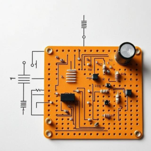
1. What is a Schematic Diagram?
A schematic diagram is like a map or blueprint for an electrical circuit. It shows how all the components (like resistors, capacitors, switches, etc.) are connected, but instead of drawing them as physical objects, it’s done using special symbols.
Think of it like a recipe or set of instructions for building a circuit, showing you what parts to use and how to connect them.

2. Why are Schematic Diagrams Important?
Schematic diagrams help:
- Understand the Circuit: They show the design clearly without the clutter of real-world details.
- Troubleshoot: If something’s wrong with a circuit, you can use the schematic to figure out where the problem might be.
- Build Circuits: If you’re building or assembling a circuit, the schematic is like the guidebook.
3. Common Symbols in Schematic Diagrams:
Instead of pictures of real components, schematics use standard symbols. Here are some of the basic ones:
- Power Source: A battery or voltage source is usually shown as two lines—one longer (positive) and one shorter (negative).
- Resistor: Represented by a zigzag line or a rectangle, it slows down the flow of current.
- Capacitor: Shown as two parallel lines, it stores energy temporarily.
- Switch: Represented as a break in the line with a toggle symbol; it opens or closes the circuit.
- Wire: Simply a line that connects components, indicating the path for electricity to flow.
4. How Do Schematic Diagrams Work?
- Connections: Lines between the symbols represent electrical wires that connect the components together.
- Direction of Current: The arrows or markings can show which way the electricity flows, though in most diagrams, the flow direction isn’t always marked.
- Ground: This is usually represented by a set of three horizontal lines, like steps, and shows where the circuit connects to the “earth” or a common reference point.
5. Example of a Simple Schematic:
Imagine you have a basic circuit with a battery, a switch, and a light bulb. The schematic might look like this:
- A battery (two lines, one long, one short).
- A switch (a line that’s open and closed).
- A light bulb (represented by a circle with an “X” in the middle).
- Wires (lines connecting everything).
In this diagram, when the switch is closed, the electrical current will flow from the battery, through the light bulb, and back to the battery, lighting it up.
6. Why Use Schematic Diagrams Instead of Real Drawings?
- Clarity: They simplify complex circuits, making it easy to see how everything is connected.
- Universality: The symbols are standard, so anyone in the world can understand them, regardless of language or where they are.
- Easier to Modify: If you want to change a circuit design, it’s much easier to tweak a schematic than redraw a physical picture.
7. Reading and Interpreting a Schematic:
When you look at a schematic, here’s how you read it:
- Start at the power source (usually the battery).
- Follow the wires to the next components.
- Look at the connections between components (the lines) to understand the flow of electricity.
- Pay attention to special symbols for things like resistors, capacitors, transistors, etc.
8. Practical Example of Using a Schematic:
Let’s say you want to build a simple flashlight. You might see a schematic diagram like this:
- A battery at the top.
- A switch that connects to a light bulb.
- A wire connecting the battery to the switch, then to the light bulb, and back to the battery.
- When you close the switch, the circuit is complete, and the light bulb will light up.
This schematic shows you the basic structure of the flashlight circuit, so when you build it, you know exactly how to connect everything.
Conclusion:
A schematic diagram is a simplified, symbolic way of representing an electrical circuit. It helps you understand how all the components are connected and guides you in building or troubleshooting the circuit. By using standard symbols and lines, schematic diagrams make it easier to design, analyze, and share electrical circuits.
Tags: battery symbol, capacitor symbol, circuit analysis, circuit assembly, circuit blueprint, circuit building, Circuit Components, circuit connections, circuit construction, circuit design, circuit symbols, circuit troubleshooting, circuit troubleshooting guide., current flow, electrical circuit, electrical components, electrical design, electrical diagrams, electrical engineering, electrical schematics, electrical wiring, electronic circuits, ground symbol, modifying circuits, power source, resistor symbol, schematic diagram, schematic interpretation, schematic reading, switch symbol, Troubleshooting Circuits, universal symbols, wire symbol


