
Testing methods for electronic circuits are used to ensure that the circuits function as expected and meet performance, safety, and quality standards. Let’s go through the most common and essential testing methods used in electronics in an easy-to-understand way.
1. Visual Inspection
This is the simplest testing method and involves carefully looking at the circuit to check for obvious problems. Technicians visually inspect the circuit boards to see if:
- Components are correctly placed
- There are no burn marks, broken parts, or loose connections
- The solder joints are good and there are no cold solder joints (which happen when the solder doesn’t melt properly)
Example: You might check if a resistor is in the correct place and if all the components are properly attached to the board.
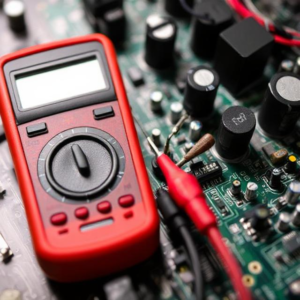
2. Continuity Testing
Continuity testing checks whether there is a complete path for current to flow through the circuit. This method is used to detect broken wires, solder joints, or missing connections in the circuit.
- Multimeters are often used for continuity testing. When the probe is placed at two points in the circuit, the multimeter beeps if the path is continuous (no breaks).
Example: You could use a multimeter to check if two points in a circuit are properly connected. If the meter beeps, it means the circuit is connected; if it doesn’t, there’s a break.
3. Voltage Testing
Voltage testing is done to measure the voltage at specific points in the circuit to ensure it matches the expected values. It is usually done with a multimeter or oscilloscope.
- DC voltage testing checks the voltage between two points in a direct current (DC) circuit.
- AC voltage testing checks voltage in an alternating current (AC) circuit.
Example: In a power supply, you could measure the voltage at the output terminals to ensure it’s delivering the correct voltage (e.g., 5V or 12V).
4. Current Testing
Current testing is used to measure the current flow through a circuit. This is important to make sure that the circuit is drawing the correct amount of current, which is crucial for the proper functioning of the circuit.
- Current is measured in amperes (A) using a multimeter or dedicated current meter.
- To measure current, the multimeter must be connected in series with the circuit (not parallel like voltage testing).
Example: If you’re testing a circuit powered by a battery, you might check how much current is flowing through the circuit to ensure it’s within the safe operating range.
5. Resistance Testing
Resistance testing helps ensure that components like resistors, capacitors, or even the circuit paths themselves have the correct resistance. This test can also detect short circuits (low resistance) or open circuits (no resistance).
- A multimeter can be used to measure resistance in ohms.
- If a resistor’s value is different from what’s expected, the circuit might not function properly.
Example: If a resistor has a value of 100 ohms, but your multimeter reads 150 ohms, it might indicate that the resistor is faulty.
6. Functional Testing
Functional testing involves checking whether the circuit or device performs its intended function. For example:
- Testing a light switch circuit to see if the light turns on and off properly.
- Testing a power supply to ensure it provides the correct output voltage under different loads.
- Checking if the circuit reacts correctly to inputs and gives the expected outputs.
Example: In a home appliance, functional testing would involve checking if the appliance operates as expected (e.g., a blender should spin its blades when turned on).
7. Oscilloscope Testing
An oscilloscope is an advanced tool used to observe the waveforms of electrical signals in real-time. This is particularly useful for testing signals in complex circuits, like microcontrollers or communication systems.
- It shows how voltage varies over time, letting you see if the circuit’s signals are behaving as expected (like pulses, sine waves, or square waves).
- An oscilloscope is especially useful for high-frequency signals and circuits where timing is important.
Example: You might use an oscilloscope to check the output waveform of a PWM signal or the operation of a clock circuit.
8. Signal Injection and Probing
This method involves injecting a known signal into the circuit and using a probe (like an oscilloscope probe) to check the output at different points.
- It’s a useful method to locate where the problem is occurring in a complex circuit.
- Engineers might inject a signal at the input of an amplifier and use a probe to check the signal at the output to ensure it has been amplified correctly.
Example: In an audio amplifier circuit, you could inject an audio signal at the input and check if the same signal comes out at the output with increased amplitude.
9. Temperature Testing
Some components, especially in power circuits, can overheat and cause problems. Temperature testing checks whether the circuit is heating up beyond its safe operating range.
- Thermal cameras or infrared thermometers are used to monitor the temperature of components like transistors or power supplies.
- Overheating components may need heat sinks or better cooling to prevent failure.
Example: If the voltage regulator in a power supply is getting too hot, it could be a sign of overloading or improper design.
10. In-Circuit Testing (ICT)
In-circuit testing is a method that checks the integrity and functionality of individual components and connections while the circuit is in operation. This method uses special test equipment to automatically test a circuit during assembly.
- It helps detect problems like wrong components, misplaced components, soldering issues, and connection problems.
- This is often used in automated testing systems for mass production.
Example: A circuit board may pass through an in-circuit tester that checks each component’s resistance, voltage, and connection.
11. Burn-In Testing
Burn-in testing involves running a circuit or device for a long period under normal or high-stress conditions to ensure it doesn’t fail over time.
- This helps detect early failures that might occur due to manufacturing defects or design issues.
- It’s particularly useful for testing high-reliability products.
Example: A power supply unit (PSU) might be run under load conditions for several hours to check for stability and performance degradation.
12. Electromagnetic Compatibility (EMC) Testing
EMC testing ensures that the device does not emit harmful electromagnetic interference (EMI) and is immune to external EMI. It’s crucial for devices that need to work in environments with sensitive electronics (like medical or aerospace applications).
- Tests include radiated emissions testing and immunity testing to ensure the device doesn’t interfere with other equipment and can function correctly in such environments.
Example: A radio receiver must be tested to ensure it doesn’t emit signals that could interfere with other communication devices.
Summary:
In electronics, testing is essential to make sure that circuits and devices are reliable, safe, and functional. From simple checks like visual inspection to advanced methods like oscilloscope testing, each testing method plays an important role in ensuring that the product works as expected.


