Series and Parallel Circuits
Electric circuits form the backbone of countless devices and systems, and they can be wired in two primary configurations: series and parallel. Each configuration governs how current flows and how voltage is distributed differently. This article explains both types in a clear and straightforward manner, highlighting their characteristics, formulas, advantages, disadvantages, and real-world applications.
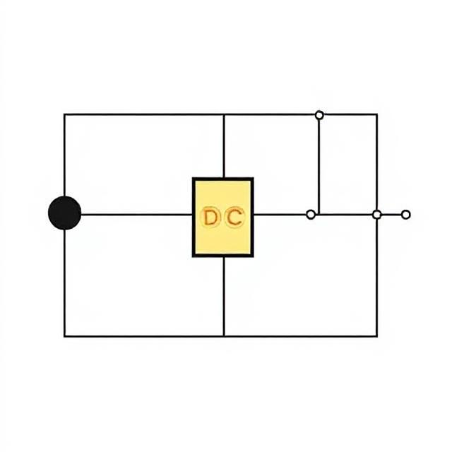
1. Series Circuits
What is a Series Circuit?
In a series circuit, components are connected sequentially in a single, continuous loop, providing only one path for the electric current to flow. If any component fails, the entire circuit ceases to function.
Example
Think of a string of traditional Christmas lights: if one bulb burns out, the whole string goes dark because the circuit is broken.
Key Points
-
Single path: Current flows through one continuous route.
-
Component failure: If one component stops working, the entire circuit fails.
-
Current consistency: The same current flows through all components.
-
Voltage distribution: The total voltage is divided across each component.
Formulas
-
Total Voltage (V): V = V₁ + V₂ + V₃ + …
-
Current (I): Remains the same across all components.
-
Total Resistance (R): R = R₁ + R₂ + R₃ + …
Advantages
-
Simple to design and construct.
-
Easy to understand and analyze.
Disadvantages
-
A single failure disables the entire circuit.
-
Less suitable for complex or critical systems.
2. Parallel Circuits
What is a Parallel Circuit?
In a parallel circuit, components are connected across the same voltage source, with each component having its own direct path to the power supply. This setup allows other paths to remain functional even if one fails.
Example
Consider modern home lighting: if one bulb fails, the others continue to shine because each bulb has its own connection to the power source.
Key Points
-
Multiple paths: Current can flow through several routes.
-
Component independence: If one component fails, others continue to operate.
-
Voltage consistency: The same voltage is applied across all branches.
-
Current distribution: The total current splits among the branches.
Formulas
-
Total Voltage (V): Remains the same for all branches.
-
Current (I): I = I₁ + I₂ + I₃ + …
-
Total Resistance (R): 1/R_total = 1/R₁ + 1/R₂ + 1/R₃ + …
Advantages
-
More reliable, as a single failure does not disrupt the entire circuit.
-
Easy to add or remove components without affecting others.
Disadvantages
-
More complex to design and analyze.
-
Requires additional wiring, increasing costs.
3. Comparison of Series and Parallel Circuits
|
Feature |
Series Circuit |
Parallel Circuit |
|---|---|---|
|
Path for Current |
Single path |
Multiple paths |
|
If One Part Fails |
Entire circuit stops |
Other parts continue working |
|
Voltage Across Parts |
Divided among components |
Same across all branches |
|
Current Through Parts |
Same through all components |
Divided among branches |
|
Total Resistance |
Sum of all resistances |
Reciprocal sum of resistances |
4. Real-Life Examples
Series Circuits
-
Flashlight: A simple circuit where the battery, switch, and bulb are connected in series.
-
Traditional Christmas Lights: A single break in the circuit darkens the entire string.
Parallel Circuits
-
Home Electrical Wiring: Outlets and lights are wired in parallel, allowing independent operation.
-
Car Headlights: Each headlight operates independently, so one failing does not affect the other.
5. Summary
-
Series circuits are ideal for simple designs where all components must function together, but they lack reliability due to their single-point failure risk.
-
Parallel circuits offer greater reliability and flexibility, making them suitable for systems where independent operation and fault tolerance are critical.

