Resonance in RLC Circuits
Resonance in an RLC circuit occurs when the inductive reactance (X_L) and capacitive reactance (X_C) are equal. At this point, their opposing effects cancel each other out, resulting in the circuit behaving like a pure resistor with minimal impedance. This leads to the circuit’s current reaching its maximum value for a given voltage. Resonance is essential in various applications, such as tuning circuits, radio receivers, and many other electronic devices.
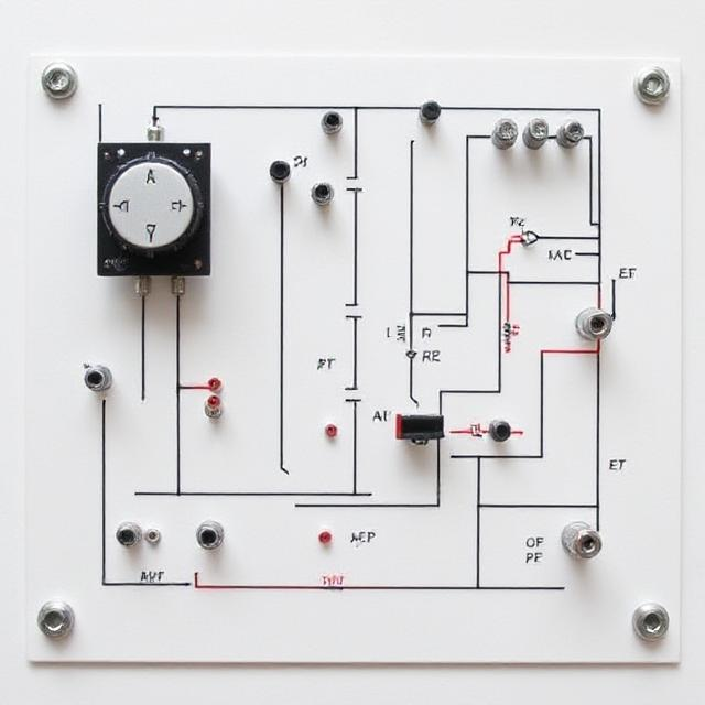
Detailed Explanation
-
What is an RLC Circuit?
An RLC circuit is an electrical circuit that includes three primary components: a resistor (R), an inductor (L), and a capacitor (C). These components can be connected in series or parallel. In alternating current (AC) circuits, these components introduce reactance, which causes phase differences between voltage and current.
-
R = Resistor: Resists the flow of current.
-
L = Inductor: Opposes changes in current.
-
C = Capacitor: Stores energy in an electric field.
In AC circuits, the interplay between these elements affects how current flows, with reactance influencing the phase difference between voltage and current.
-
Reactance in RLC Circuits
-
Inductive Reactance (X_L): Inductive reactance increases with frequency and is given by the formula:
Where:
-
f = frequency (Hz)
-
L = inductance (H)
-
-
Capacitive Reactance (X_C): Capacitive reactance decreases with frequency and is given by the formula:
Where:
-
f = frequency (Hz)
-
C = capacitance (F)
-
Reactance is measured in ohms (Ω) and causes phase differences between voltage and current in the circuit.
-
What is Resonance?
Resonance in an RLC circuit occurs when the inductive reactance (X_L) is equal to the capacitive reactance (X_C):
Or, equivalently:
At this specific frequency, known as the resonant frequency (f₀), the effects of the inductor and capacitor cancel each other out, causing the total reactance to be zero.
-
Resonant Frequency Formula
The formula to calculate the resonant frequency (f₀) is:
Where:
-
f₀ is the resonant frequency in hertz (Hz)
-
L is the inductance in henries (H)
-
C is the capacitance in farads (F)
-
What Happens at Resonance?
At resonance, the total reactance of the circuit is zero:
As a result:
-
The circuit’s impedance is minimized and equals the resistance (R):
-
The current reaches its maximum value for the applied voltage.
-
Voltage and current are in phase, meaning there is no phase difference between them.
-
The circuit can efficiently store and exchange energy between the inductor and capacitor.
-
Types of Resonance Circuits
-
Series Resonance: In this configuration, the resistor, inductor, and capacitor are connected in series. Resonance occurs when the total reactance is zero, and the impedance is minimized to the resistance.
-
Parallel Resonance: In this setup, the components are connected in parallel. While resonance still occurs, the behavior of the impedance and current differs from that of the series resonance circuit.
-
Importance of Resonance
Resonance plays a critical role in various applications, including:
-
Tuning Circuits: Used in radios, televisions, and communication systems to select specific frequencies.
-
Filters: Allow certain frequencies to pass through while blocking others.
-
Energy Transfer: Enhances energy transfer in systems like wireless power transfer.
-
Quality Factor (Q)
The Quality Factor (Q) of a resonance circuit describes the sharpness of the resonance. It is defined as the ratio of the resonant frequency to the bandwidth:
-
A high Q indicates sharp resonance with a narrow bandwidth.
-
A low Q suggests a broad resonance with a wider bandwidth.
-
Summary
| Property | Description |
|---|---|
| Resonant Frequency (f₀) | Frequency where X_L = X_C |
| Impedance at Resonance | Minimum, equal to R |
| Current at Resonance | Maximum |
| Phase Difference | Zero (Voltage and current in phase) |
| Application | Radio tuning, filters, wireless power |
Conclusion
Resonance in RLC circuits is a crucial concept in AC circuit theory. It allows circuits to selectively respond to specific frequencies with minimal impedance and maximum current. Understanding resonance is essential for the design and operation of communication systems, signal processing, and efficient power transfer technologies.

