
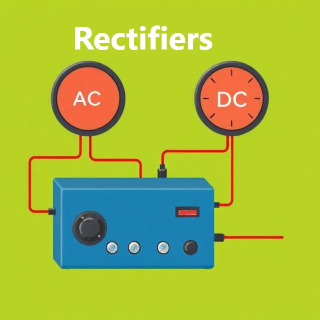
A rectifier circuit is used to convert alternating current (AC) to direct current (DC). This is important because many electronic devices require DC power to operate, but the electrical supply is typically in AC form. Diodes are essential components in rectifiers as they allow current to flow in only one direction, effectively converting AC to DC.
What is a Rectifier Circuit?
A rectifier is a circuit that changes alternating current (AC) into direct current (DC). This conversion is done using diodes, which are electronic components that allow current to flow in one direction only. In a rectifier circuit, the diode acts as a one-way valve for the electric current, ensuring that the current flows in a single direction, thus creating a unidirectional output that is DC.
There are two main types of rectifier circuits:
-
Half-Wave Rectifier
-
Full-Wave Rectifier
1. Half-Wave Rectifier
In a half-wave rectifier, the diode only allows current to pass during one half of the AC signal cycle (either the positive or negative half). The output of a half-wave rectifier is a pulsating DC signal, which means that it’s not smooth or continuous.
Working of Half-Wave Rectifier:
-
When the AC input is positive, the diode conducts, allowing current to pass.
-
When the AC input is negative, the diode does not conduct, and no current flows.
The result is a series of pulses, creating a DC signal but with gaps between the pulses.
Limitations:
-
The output is not smooth and has a lot of ripple.
-
It is inefficient because only half of the AC waveform is used.
2. Full-Wave Rectifier
A full-wave rectifier converts both halves of the AC signal into DC. This means that the diode conducts during both the positive and negative cycles of the AC input. The result is a smoother DC signal compared to the half-wave rectifier.
There are two types of full-wave rectifiers:
-
Center-Tapped Full-Wave Rectifier
-
Bridge Rectifier
Center-Tapped Full-Wave Rectifier:
-
This circuit uses two diodes and a transformer with a center-tapped secondary winding.
-
The center tap acts as a ground, and the diodes alternate between conducting during the positive and negative cycles of the AC input.
Bridge Rectifier:
-
The bridge rectifier uses four diodes arranged in a bridge configuration. This type of rectifier does not require a center-tapped transformer.
-
During both the positive and negative cycles of the AC input, two diodes conduct at a time, ensuring that current always flows in the same direction through the load.
Advantages of Full-Wave Rectifier:
-
It is more efficient than a half-wave rectifier because it uses both halves of the AC input.
-
The output is smoother, with less ripple.
Smoothing the Output
While rectifiers provide DC output, this DC is often pulsating. To get a steady, smooth DC output, a filter is added to the rectifier circuit. The most common filter is a capacitor, which smooths out the ripples by storing charge and releasing it when the voltage drops.
Summary
Rectifier circuits are essential for converting AC to DC, and diodes play a crucial role in this process.
-
Half-wave rectifiers are simple but inefficient, as they only use half of the AC signal and produce a pulsating DC output.
-
Full-wave rectifiers are more efficient, using both halves of the AC waveform and producing a smoother DC output. They can be configured as center-tapped or bridge rectifiers.
-
Smoothing the output of a rectifier is done using capacitors to reduce ripple and achieve a stable DC output.


 : Explain")


