

What is an Oscilloscope?
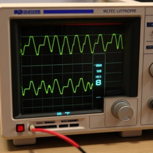
An oscilloscope is an electronic device used to visualize electrical signals. It shows how voltage changes over time, allowing you to see the waveforms of signals in a graph format. Imagine it as a screen that helps you see the invisible electrical signals that are usually flowing through wires or circuits.
How Does an Oscilloscope Work?
- Signal Input: The oscilloscope receives an electrical signal from the device or circuit you want to analyze. This could be a signal from a power supply, an audio signal, or any other electrical signal.
- Graphical Display: It then displays that signal on the screen as a waveform (a line graph), with:
- The x-axis (horizontal) representing time (how the signal changes over time).
- The y-axis (vertical) representing voltage (how strong the signal is).
- Waveform: The waveform shows how the voltage of the signal fluctuates. You can see if the signal is steady, oscillating, or changing in any way, and measure important characteristics like the signal’s frequency and amplitude.
Main Parts of an Oscilloscope:
- Display Screen: This is where you see the waveform. Modern oscilloscopes have digital screens, while older models used analog displays.
- Probes: These are connected to the circuit or device you want to measure. They bring the signal into the oscilloscope for display.
- Controls: The oscilloscope has knobs and buttons to control things like:
- Time base: Adjusts how much time is shown on the x-axis (horizontal), letting you zoom in or out to see more or less time.
- Voltage scale: Adjusts how much voltage is shown on the y-axis (vertical), helping you zoom in or out to see the strength of the signal.
- Trigger: Helps stabilize the waveform so it stays steady on the screen.
- Channels: Oscilloscopes can have one or more channels to measure and display multiple signals at once.
Types of Oscilloscopes:
- Analog Oscilloscope: This is the traditional type. It shows the waveform in real-time using cathode-ray tubes (CRTs), much like an old television screen.
- Digital Oscilloscope: More common today, it converts the signal to digital data and displays it on an LCD screen. Digital oscilloscopes are often more accurate, flexible, and come with additional features like storage, measurement, and analysis.
- Mixed Signal Oscilloscope (MSO): This is a more advanced version that combines the features of an oscilloscope with a logic analyzer, making it useful for both analog and digital signals.
What are Oscilloscopes Used For?
Oscilloscopes are used in many areas of electronics and electrical engineering to diagnose, analyze, and design circuits. Here are some of their main uses:
1. Viewing Waveforms
- Why it’s important: The oscilloscope helps you “see” the signals in a circuit to understand how they behave. For example, you can see the shape of an audio signal, whether a square wave is stable, or if there’s any noise in a signal.
2. Measuring Signal Characteristics
- Amplitude: How tall or strong the signal is.
- Frequency: How fast the signal oscillates (how often it repeats).
- Period: The time it takes for one cycle of the signal to complete.
- Peak-to-Peak Voltage: The difference between the highest and lowest voltage in the signal.
3. Troubleshooting Circuits
- Why it’s important: When something isn’t working in an electronic circuit, an oscilloscope helps you find the problem. For example, if a signal is distorted, missing, or too weak, you can see that directly on the screen and identify where the issue is.
4. Testing Electronics Components
- Why it’s important: You can test the performance of components like transistors, resistors, and capacitors by examining how they influence the signal. For example, you can see if a capacitor is filtering a signal properly or if a signal is distorted due to a faulty component.
5. Designing and Debugging Circuits
- Why it’s important: Engineers and designers use oscilloscopes to test their circuit designs. They can observe how the circuit performs in real-time, adjusting it to ensure the signals behave as expected.
6. Measuring Timing in Digital Systems
- Why it’s important: Oscilloscopes are not just for analog signals—they’re also used in digital electronics to check things like timing, signal integrity, and digital pulses.
7. Verifying Communication Signals
- Why it’s important: In communication systems, oscilloscopes can help verify that signals like radio waves or network signals are being transmitted properly.
Example of Using an Oscilloscope:
Let’s say you are designing a power supply circuit. You might connect an oscilloscope to the output of the power supply to make sure the voltage is stable and within the expected range. If the waveform on the oscilloscope looks jagged or fluctuates, it indicates there’s an issue with the supply—perhaps a faulty component or design flaw.
Why Oscilloscopes Are Important:
- Precision: They give precise and clear insights into electrical signals that would be hard to diagnose otherwise.
- Time-saving: By showing signals visually, they help engineers quickly pinpoint problems and improve designs.
- Versatility: They can be used in a wide range of applications, from simple audio testing to complex digital and communication systems.
Conclusion:
An oscilloscope is a powerful tool that helps you “see” electrical signals in real-time, so you can understand how they behave and troubleshoot any issues. Whether you’re designing a circuit, fixing a malfunction, or measuring a signal’s properties, an oscilloscope is an essential tool for anyone working with electronics.
Tags: analog oscilloscope, capacitor testing, circuit design, circuit troubleshooting, communication signal verification, Component Testing, CRT display, debugging, digital oscilloscope, digital pulses, electrical engineering tool, electrical signals, electrical waveform view, electronic device, electronics diagnostics, LCD screen, mixed signal oscilloscope, multiple channels, noise analysis, oscilloscope, Oscilloscopes, peak-to-peak voltage, power supply testing, precision measurement, probes, real-time signal monitoring, Resistor testing, signal amplitude, signal analysis, signal distortion detection, Signal frequency, signal graph, Signal Integrity, signal period, signal waveform display, time axis, time base, timing measurement, Transistor testing, trigger control, versatile measurement tool, voltage axis, voltage over time, voltage scale, waveform stability, waveform visualization