I2C (Inter-Integrated Circuit) Communication Protocol
I2C (pronounced as “I-squared-C” or “I-two-C”) is a serial communication protocol commonly used for connecting microcontrollers to various peripheral devices, such as sensors, EEPROMs, ADCs, DACs, and more, over short distances. It was developed by Philips (now NXP Semiconductors) in the 1980s for communication between ICs within a system.

Key Features of I2C:
- Two-Wire Interface: I2C uses only two wires for communication, making it simple and efficient for low-speed applications.
- SDA (Serial Data Line): Carries the data between devices.
- SCL (Serial Clock Line): Carries the clock signal, synchronized with the data transfer.
- Multi-Master and Multi-Slave: I2C supports multiple masters (controllers) and multiple slaves (peripheral devices) on the same bus. However, only one master can control the bus at a time.
- Addressing: Each device on the bus is identified by a unique address. Typically, I2C uses 7-bit or 10-bit addresses.
- Half-Duplex Communication: Data is transferred in one direction at a time (either transmitting or receiving).
I2C Bus Structure:
- Master: The device that initiates and controls communication. It generates clock signals and can read/write to slave devices.
- Slave: Devices that respond to the master’s requests. Each slave has a unique address.
Communication Protocol:
The I2C protocol works in the following steps:
- Start Condition (S):
- The communication begins when the master pulls the SDA line low while SCL is high. This is called a start condition, signaling the beginning of a transmission.
- Addressing:
- After the start condition, the master sends the 7-bit address of the slave device followed by a read/write bit.
- If the write bit is ‘0’, the master intends to send data to the slave.
- If the write bit is ‘1’, the master intends to receive data from the slave.
- Example of a 7-bit address format: 7 bits of address + 1 read/write bit (total 8 bits).
- After the start condition, the master sends the 7-bit address of the slave device followed by a read/write bit.
- Acknowledge (ACK) and No-Acknowledge (NACK):
- After each byte of data is transmitted, the receiver (master or slave) sends an acknowledge (ACK) signal by pulling the SDA line low for one clock pulse.
- If the receiver is not ready to receive or if there’s no data to send, it sends a No-Acknowledge (NACK) signal by leaving the SDA line high during the acknowledge phase.
- Data Transfer:
- Data is sent in 8-bit chunks (1 byte) over the SDA line, synchronized with the clock signal on the SCL line.
- Each byte of data is followed by an ACK/NACK response.
- Stop Condition (P):
- After the data transfer is complete, the master generates a stop condition by pulling SDA high while SCL is high. This indicates the end of the communication.
Data Transfer Example:
Let’s say a master wants to read data from a slave device with address 0x50. Here’s the sequence:
- Start Condition (S)
- Address + Write (0x50 | Write = 0): Master sends 0xA0 (binary: 10100000) to select slave 0x50 and specify a write operation.
- ACK from Slave
- Send Data (optional if writing): Master can now send data to slave, byte by byte, and receive ACK after each byte.
- Restart Condition (Repeated Start, if applicable): Master may initiate a repeated start condition to switch to reading mode without releasing the bus.
- Address + Read (0x50 | Read = 1): Master sends 0xA1 to indicate it wants to read from slave 0x50.
- ACK from Slave
- Slave Data: Slave sends data byte(s) to the master.
- ACK from Master (except for the last byte)
- Stop Condition (P): Master sends a stop condition to end the communication.
I2C Data Transfer Timing Diagram:
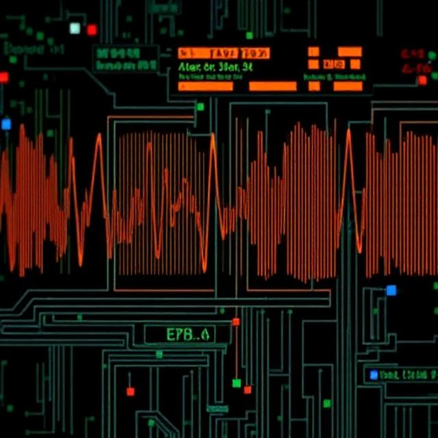
The timing of an I2C transfer is synchronous with the clock (SCL), and data is shifted out on SDA on each rising or falling edge of the clock. Here’s a brief overview of timing:
- Data Setup Time: Data on SDA should be stable before the clock edge.
- Data Hold Time: Data on SDA should stay stable after the clock edge.
- Clock Pulse: The SCL line determines the speed of the communication (standard mode 100kHz, fast mode 400kHz, or high-speed mode 3.4MHz).
Advantages of I2C:
- Simple Design: Only two lines (SDA and SCL) are needed for communication, simplifying circuit design.
- Multiple Devices: I2C can support multiple devices on a single bus using unique addresses.
- Reduced Pin Usage: As only two lines are used, fewer pins on the microcontroller are required compared to other communication protocols like SPI or UART.
- Slower but Robust: It’s typically used for relatively low-speed communication (up to 400 kHz), but it is robust enough for sensor readings, EEPROM accesses, and small peripheral connections.
Limitations of I2C:
- Speed: I2C is not as fast as other communication protocols like SPI, especially at high-speed data transfer.
- Limited Range: I2C is suitable for short-distance communication; for long-distance communication, other protocols like RS-485 may be preferred.
- Bus Contention: When multiple masters are present, bus contention can occur if two masters try to take control of the bus simultaneously.
Conclusion:
I2C is a versatile and efficient protocol for communication between microcontrollers and peripheral devices. Its simplicity (only two lines) and ability to support multiple devices make it suitable for applications such as sensor interfaces, real-time clocks, and EEPROMs. However, for higher-speed or long-distance communication, other protocols might be more suitable.


