What is Digital Electronics?
Digital electronics is a branch of electronics that deals with systems or devices that use digital signals to process and store information. These systems work with binary numbers (0s and 1s), meaning the information is represented by two states: ON (1) and OFF (0).
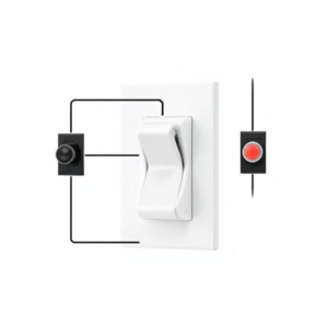
You can think of it like flipping a light switch. Either the light is on (1) or it’s off (0). Digital electronics takes advantage of this simple idea to do complex tasks

How Does Digital Electronics Work?
Digital electronics uses binary (base-2) number system. In this system, numbers are made up of just two digits: 0 and 1.
Example:
- The number 1011 in binary means:
- 1 is ON
- 0 is OFF
- 1 is ON
- 1 is ON
These 0s and 1s are used to represent information in a form that computers and other digital systems can understand. These 0s and 1s are stored and processed using digital circuits.
Key Components of Digital Electronics
1. Logic Gates
- What are they? Logic gates are the building blocks of digital electronics. They perform basic operations on binary inputs to produce a binary output.
- Examples of Logic Gates:
- AND gate: Only gives a “1” (ON) output if both inputs are 1. If either input is 0, the output is 0.
- OR gate: Gives a “1” if either input is 1.
- NOT gate: Reverses the input (makes 1 become 0, and 0 become 1).
- NAND, NOR, XOR gates are variations that combine AND, OR, and NOT operations.
These gates are combined to make digital circuits that perform more complex tasks.
2. Flip-Flops
- What are they? Flip-flops are circuits used to store binary data. They can remember a “0” or a “1” even after the input changes. They’re like tiny memory devices in digital circuits.
- Why it’s important: Flip-flops are used in things like memory (RAM), counters, and registers to hold and store information temporarily.
3. Binary Numbers and Arithmetic
- In digital electronics, all data is processed using binary numbers.
- Example: To add two binary numbers, you follow simple rules, just like adding decimal numbers, but with only 0s and 1s. For example:
- 1 + 1 = 10 (which is 2 in decimal).
- Why it’s important: These binary calculations allow digital devices (like computers) to do complex tasks like adding numbers, multiplying, or even more advanced operations.
Applications of Digital Electronics
Digital electronics is everywhere! Here are some everyday examples of where it is used:
- Computers: The heart of a computer is its digital circuit. It processes and stores data using binary numbers.
- Mobile Phones: From making calls to running apps, mobile phones rely on digital electronics to convert signals into binary data.
- TVs and Radios: Modern TVs and radios use digital signals to transmit, decode, and process audio and video.
- Digital Watches and Clocks: They use digital circuits to display the time in numbers, often using binary counting.
- Calculators: They process your inputs and perform arithmetic using digital logic.
Why is Digital Electronics Important?
- Reliability: Digital circuits are less affected by noise and interference compared to analog systems. A signal can either be “1” (ON) or “0” (OFF), which makes them more reliable and accurate.
- Speed and Power: Digital circuits can process information very quickly and efficiently, often using less power than analog systems.
- Flexibility: Digital systems are easy to modify with software and can perform a variety of tasks, unlike analog systems which are typically harder to change.
Digital Electronics: An Easy Explanation
Digital electronics deals with circuits that work with digital signals (signals that have discrete values, like 0 and 1, instead of continuous values). These circuits are the backbone of modern electronic devices like computers, mobile phones, and TVs.
Let’s go step by step to explain some of the most important components of digital electronics!
1. Logic Gates
Logic gates are the building blocks of digital electronics. They take one or more binary inputs (0 or 1) and produce a binary output (0 or 1) based on certain rules. There are several basic types of logic gates:
- AND Gate:
- What it does: The output is 1 only when both inputs are 1. If any input is 0, the output is 0.
- Example: Input A = 1, Input B = 1 → Output = 1. But, if A = 0 and B = 1, Output = 0.
- OR Gate:
- What it does: The output is 1 if either of the inputs is 1. If both inputs are 0, the output is 0.
- Example: Input A = 0, Input B = 1 → Output = 1.
- NOT Gate:
- What it does: It inverts the input. If the input is 0, the output is 1, and if the input is 1, the output is 0.
- Example: Input A = 1 → Output = 0.
- XOR Gate (Exclusive OR):
- What it does: The output is 1 only when one input is 1 and the other is 0. If both inputs are the same (either both 0 or both 1), the output is 0.
- Example: Input A = 1, Input B = 0 → Output = 1. But A = 1, B = 1 → Output = 0.
- NAND Gate:
- What it does: It’s the opposite of the AND gate. The output is 0 only when both inputs are 1. For all other input combinations, the output is 1.
- Example: A = 1, B = 1 → Output = 0.
- NOR Gate:
- What it does: It’s the opposite of the OR gate. The output is 0 when either input is 1. It only gives an output of 1 when both inputs are 0.
- Example: A = 0, B = 0 → Output = 1. But A = 1, B = 0 → Output = 0.
2. Flip-Flops
A flip-flop is a basic memory unit in digital electronics that stores one bit of information. It has two stable states, and it changes between these states based on inputs and control signals. Flip-flops are used in memory storage and timing circuits.
There are several types of flip-flops:
- SR Flip-Flop (Set-Reset Flip-Flop):
- It has two inputs: S (Set) and R (Reset). It stores a bit based on these inputs.
- S = 1 sets the output to 1, and R = 1 resets the output to 0. If both are 0, the state remains unchanged.
- D Flip-Flop (Data Flip-Flop):
- It has one data input D and a clock input. The output Q takes the value of D when the clock signal triggers it. It’s commonly used for data storage.
- Example: If D = 1, the output Q will be 1 when the clock pulses.
- JK Flip-Flop:
- It is an improved version of the SR flip-flop, where the J input works like S (Set), and K works like R (Reset). When both inputs are high (J = K = 1), it toggles the output.
- T Flip-Flop (Toggle Flip-Flop):
- It has a single input T. When T = 1, it toggles the output between 0 and 1 with every clock pulse. If T = 0, it holds the previous state.
3. Counters and Registers
- Counters:
- A counter is a circuit that counts the number of clock pulses. It can count in various ways (up or down) and is used in applications like timers, clocks, and frequency dividers.
- Example: A 4-bit counter can count from 0 to 15 (0000 to 1111) and then reset to 0.
- Registers:
- A register is a small storage unit in a computer that holds multiple bits of data temporarily. Registers are used to store data being processed.
- Example: A 16-bit register can store data like 1101010101010101.
- Counters and Registers in Action:
- Example: In a digital clock, counters are used to track the seconds, minutes, and hours, while registers store the data for each time unit.
4. Multiplexers and Demultiplexers
- Multiplexer (MUX):
- A multiplexer is a device that takes multiple input lines and selects one to pass through to the output based on a select signal. It is often called a data selector.
- Example: A 4-to-1 multiplexer can take 4 input signals (A, B, C, D) and select one of them to pass to the output depending on the select lines (00, 01, 10, or 11).
- Demultiplexer (DEMUX):
- A demultiplexer does the reverse. It takes a single input signal and sends it to one of many output lines based on a select signal.
- Example: A 1-to-4 demux takes a single input signal and passes it to one of the four outputs (O1, O2, O3, O4) based on the select lines.
- Why are MUX and DEMUX important?
- Multiplexers help in saving wiring and combining data, while demultiplexers help in distributing data to multiple channels.
5. Digital-to-Analog and Analog-to-Digital Conversion
- Digital-to-Analog Conversion (DAC):
- A DAC converts digital data (0s and 1s) into an analog signal. It takes a digital number and transforms it into a continuous signal.
- Example: A sound card in a computer uses a DAC to convert the digital audio file into analog signals that can be played through speakers.
- Analog-to-Digital Conversion (ADC):
- An ADC converts analog signals (like sound or temperature) into digital data (0s and 1s) that a computer or digital device can process.
- Example: A microphone captures sound as an analog signal, and the ADC converts it into digital data so it can be processed by a computer.
- Why is Conversion Needed?
- Digital devices like computers understand only digital signals, but many real-world signals (like sound or light) are analog. So, ADC and DAC are essential to connect the real world to digital systems.
Summary
- Logic Gates: The basic building blocks of digital circuits that perform logical operations like AND, OR, NOT, XOR, etc.
- Flip-Flops: Memory units that store one bit of data. Types include SR, D, JK, and T flip-flops.
- Counters and Registers: Counters count clock pulses, and registers temporarily store data. They are used in clocks, timers, and processors.
- Multiplexers and Demultiplexers: MUX selects one input from many, while DEMUX sends a single input to one of many outputs.
- ADC and DAC: ADC converts analog signals to digital data, and DAC converts digital data back to analog signals.
Digital electronics are crucial in modern technology because they form the foundation for almost all modern electronic systems like computers, phones, and entertainment devices.


