What is a Digital Circuit?
A digital circuit is a type of electronic circuit that operates using digital signals (i.e., signals that have discrete values). These signals can only be in one of two states: ON (1) or OFF (0). These states are often represented by voltage levels: for example, high voltage (usually 5V or 3.3V) can represent 1 (ON), and low voltage (0V) can represent 0 (OFF).
Digital circuits are used in almost everything today, from computers to smartphones to TVs. They’re the backbone of modern electronics because they process binary data (which is made up of 0s and 1s).

What are Logic Gates?
Logic gates are the building blocks of digital circuits. They are simple devices that perform basic operations on one or more binary inputs to produce a single output.
Here are the basic types of logic gates:
1. AND Gate
- Symbol: A flat shape, with two or more input lines and one output line.
- Operation: The output is 1 (ON) only if all inputs are 1 (ON). If any input is 0 (OFF), the output will be 0 (OFF).Truth Table:
Input A Input B Output (A AND B) 0 0 0 0 1 0 1 0 0 1 1 1
2. OR Gate
- Symbol: A curved shape, with two or more input lines and one output line.
- Operation: The output is 1 (ON) if at least one of the inputs is 1 (ON). The output will only be 0 (OFF) if all inputs are 0 (OFF).Truth Table:
Input A Input B Output (A OR B) 0 0 0 0 1 1 1 0 1 1 1 1
3. NOT Gate (Inverter)
- Symbol: A triangle pointing to a small circle (indicating negation).
- Operation: The output is the opposite of the input. If the input is 0 (OFF), the output will be 1 (ON). If the input is 1 (ON), the output will be 0 (OFF).Truth Table:
Input Output (NOT A) 0 1 1 0
4. NAND Gate
- Symbol: Looks like an AND gate, but with a small circle (NOT) on the output.
- Operation: The output is 1 (ON) except when all inputs are 1 (ON). If all inputs are 1, the output will be 0 (OFF). It’s essentially the opposite of the AND gate.Truth Table:
Input A Input B Output (A NAND B) 0 0 1 0 1 1 1 0 1 1 1 0
5. NOR Gate
- Symbol: Looks like an OR gate, but with a small circle (NOT) on the output.
- Operation: The output is 0 (OFF) except when all inputs are 0 (OFF). If all inputs are 0, the output will be 1 (ON). It’s the opposite of the OR gate.Truth Table:
Input A Input B Output (A NOR B) 0 0 1 0 1 0 1 0 0 1 1 0
6. XOR Gate (Exclusive OR)
- Symbol: Looks like an OR gate with an extra curve.
- Operation: The output is 1 (ON) if only one of the inputs is 1 (ON). If both inputs are the same (either both 0 or both 1), the output is 0 (OFF).Truth Table:
Input A Input B Output (A XOR B) 0 0 0 0 1 1 1 0 1 1 1 0
7. XNOR Gate (Exclusive NOR)
- Symbol: Looks like an XOR gate, but with a small circle (NOT) on the output.
- Operation: The output is 1 (ON) if both inputs are the same. If the inputs are different, the output will be 0 (OFF). It is the opposite of the XOR gate.Truth Table:
Input A Input B Output (A XNOR B) 0 0 1 0 1 0 1 0 0 1 1 1
Combining Logic Gates to Create Digital Circuits
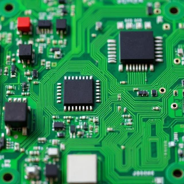
Digital circuits often combine many logic gates to perform more complex tasks. For example, in a computer’s processor, billions of tiny gates work together to process data, perform calculations, and control the flow of information.
Applications of Digital Circuits
- Computers: Everything in a computer, from basic calculations to complex decision-making, is done by digital circuits.
- Smartphones: Digital circuits control the display, processor, memory, and many other functions.
- Consumer Electronics: TVs, microwaves, and even washing machines use digital circuits for various tasks.
- Communication Systems: Digital circuits help encode and decode data for transmission in mobile phones and the internet.
Summary
- Digital circuits work with binary signals (0s and 1s), and logic gates perform basic operations on those signals.
- The main types of gates are AND, OR, NOT, NAND, NOR, XOR, and XNOR.
- These gates are combined to build complex systems that power most of today’s technology.


