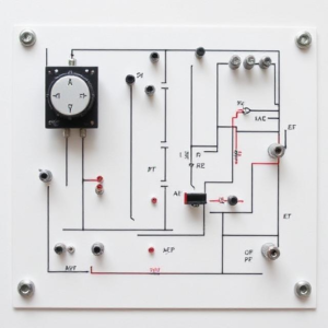
1. What is a DC Circuit?
A DC (Direct Current) circuit is a type of electrical circuit where the current flows in one direction only. The voltage across the components in a DC circuit doesn’t change over time, meaning it stays constant. In contrast, AC (Alternating Current) circuits have current that changes direction periodically.
Imagine a battery-powered circuit. The current flows from the positive side of the battery, through the circuit, and back to the negative side in a single direction. This is an example of a DC circuit.

2. Basic Components of a DC Circuit
To understand DC circuits, you need to know about some basic components that make up the circuit:
a. Voltage Source
- A voltage source (like a battery or a DC power supply) provides the electrical pressure (called voltage) that pushes the current through the circuit. In a battery, for example, the positive terminal provides high potential, and the negative terminal provides low potential.
b. Resistor
- A resistor is a component that resists or slows down the flow of current. It’s like a narrow pipe in a water system that makes it harder for water to flow through.
- In a DC circuit, the resistor helps control how much current flows based on the voltage applied.
c. Capacitor (optional in DC)
- A capacitor stores electrical energy temporarily. In DC circuits, capacitors charge up to the supply voltage and then stay charged. They are more commonly used in AC circuits, but they can be used in DC circuits for specific functions, like smoothing the voltage.
d. Inductor (optional in DC)
- An inductor is a coil of wire that stores energy in a magnetic field when current flows through it. In a DC circuit, inductors mostly have an immediate effect when the current is first applied, but once the current reaches a steady state, the inductor doesn’t affect the circuit much.
3. Ohm’s Law – The Foundation of DC Circuit Theory
The most important rule in DC circuit theory is Ohm’s Law. It helps us understand the relationship between voltage, current, and resistance in a circuit.
Ohm’s Law states:
Where:
- V is the voltage (in volts, V).
- I is the current (in amperes, A).
- R is the resistance (in ohms, Ω).
This means:
- If you know any two of these values (voltage, current, resistance), you can easily calculate the third one.
- For example, if you have a 9V battery and a 3Ω resistor, the current flowing through the circuit would be:
So, 3 amps of current will flow.
4. Series and Parallel Circuits in DC
DC circuits can be connected in different ways, and the two main types are series circuits and parallel circuits.
a. Series Circuit
- In a series circuit, components are connected end-to-end, meaning there is only one path for the current to flow.
- The current is the same throughout the entire circuit, but the voltage is divided across the components.
- Example: If you have three resistors in series, the total resistance will be the sum of all the resistances.
So, if the resistors are 2Ω, 3Ω, and 5Ω, the total resistance is 10Ω.
b. Parallel Circuit
- In a parallel circuit, components are connected across common points. This means there are multiple paths for the current to flow.
- The voltage is the same across all components, but the current is divided based on the resistance.
- Example: If you have three resistors in parallel, the total resistance is calculated differently:
If you have 2Ω, 3Ω, and 6Ω resistors in parallel, the total resistance will be less than any individual resistance.
5. Kirchhoff’s Laws in DC Circuits
There are two key laws that help analyze DC circuits: Kirchhoff’s Voltage Law (KVL) and Kirchhoff’s Current Law (KCL).
a. Kirchhoff’s Voltage Law (KVL)
- KVL states that the sum of all the voltages around any closed loop in a circuit is always zero. This is because the total energy provided by the sources (like batteries) is used up by the components (like resistors).
- In other words, if you go around a loop in a circuit and add up all the voltage drops (the resistors, capacitors, etc.), the total will equal the voltage supplied by the source.
b. Kirchhoff’s Current Law (KCL)
- KCL states that the sum of currents entering a junction in a circuit is equal to the sum of currents leaving the junction. This is because electric charge is conserved. No charge is lost at any junction.
- For example, if three currents meet at a point, the sum of the currents entering will equal the sum of the currents leaving.
6. Power in DC Circuits
The power in a DC circuit is the rate at which electrical energy is used or produced. It can be calculated using the formula:
Where:
- P is the power (in watts, W).
- V is the voltage (in volts, V).
- I is the current (in amperes, A).
For example, if a resistor has a voltage of 12V across it and the current flowing is 2A, the power used by the resistor is:
This means the resistor is using 24 watts of power.
7. Practical Example of a DC Circuit
Let’s put this all together with a simple example:
You have a circuit with a 9V battery and a 3Ω resistor.
- First, we use Ohm’s Law to find the current:
So, 3 amps of current flow through the circuit.
- If you wanted to calculate the power consumed by the resistor:
So the resistor is using 27 watts of power.
8. Conclusion
To summarize:
- A DC circuit is a circuit where the current flows in one direction, driven by a constant voltage source (like a battery).
- Ohm’s Law is the key principle, which relates voltage, current, and resistance.
- There are series circuits (components in a line) and parallel circuits (components with multiple paths for current).
- Kirchhoff’s Laws help in analyzing complex circuits: KVL (voltage in a loop adds up to zero) and KCL (current entering a junction equals current leaving).
- Power in DC circuits is calculated as P = V x I.
With this foundation, you can start analyzing and solving basic DC circuits! Let me know if you’d like to dive into specific examples or concepts!
Keywords: circuit, Electronics


