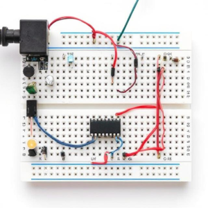
A breadboard is a tool used to build and test electronic circuits without the need for soldering. It’s like a reusable platform where you can quickly set up circuits and experiment with different designs. It’s commonly used by engineers, hobbyists, and students to prototype (test ideas) before making a permanent version of the circuit.
Here’s a simple explanation of breadboards and how they work:

1. What is a Breadboard?
A breadboard is a flat board with lots of holes (also called sockets) that allow you to insert electronic components like resistors, capacitors, and wires. The components are connected by metal strips inside the board that run horizontally and vertically. These metal strips create connections between the components, making it easy to test a circuit.
Parts of a Breadboard:
- Rows and Columns: The breadboard has rows of holes, each of which is electrically connected. Most breadboards have:
- Horizontal rows (these rows are usually used for connecting power rails or ground connections).
- Vertical columns (used for connecting components).
- Power Rails: Usually found on the sides of the breadboard, these are long columns marked with a “+” (positive) and a “−” (negative or ground) to provide power to the circuit.
- Buses (Metal Strips): Inside the breadboard, there are metal strips that connect the holes in the rows and columns. These metal strips allow electrical signals to flow between components placed in the same row or column.
2. How Does a Breadboard Work?
A breadboard works by providing an easy way to connect electronic components together without the need for permanent connections (like soldering). The components are inserted into the holes and automatically connected to other components through the metal strips inside the breadboard.
Example:
- If you insert a resistor into one row, it is connected to any other component (like an LED) placed in the same row because the metal strips inside the breadboard are connected.
- The power rails at the side are used to supply power to the circuit, where you can connect the positive side of a power supply to the “+” rail and the negative side to the “−” rail.
3. Building a Circuit on a Breadboard
Step-by-Step Process:
- Planning the Circuit: Before using the breadboard, it’s important to know what circuit you want to build. You may want to sketch a simple diagram or schematic of your circuit.
- Placing Components: Start by inserting the components (resistors, LEDs, transistors, etc.) into the breadboard.
- Insert the legs (leads) of the components into the holes on the breadboard. The legs should fit snugly into the holes so they make a connection with the metal strips inside.
- Make sure to connect each component according to your circuit design (for example, connect the anode of an LED to the power rail and the cathode to ground).
- Connecting the Components: Use jumper wires (short wires) to connect different parts of the circuit.
- You can use the same row for connecting components. For example, if you’re connecting a resistor to an LED, insert both components in the same row and use wires to make other necessary connections.
- If you need to connect different parts of the breadboard (e.g., from one side to the other), you can use jumper wires to bridge the gap.
- Powering the Circuit: Connect the power supply or battery to the power rails.
- Connect the positive terminal of your power source to the “+” rail, and the negative terminal to the “−” rail.
- Testing the Circuit: Once everything is connected, you can power up the circuit and check if it works as expected.
- You can test LEDs, measure voltages with a multimeter, or check if switches and sensors are functioning properly.
4. Advantages of Using a Breadboard
- No Soldering Required: You can quickly test and modify your circuits without needing to solder components together. This makes breadboards perfect for experimenting and prototyping.
- Reusable: You can reuse the breadboard for different projects. Components can easily be removed and placed again in different positions.
- Quick and Easy: Setting up a circuit on a breadboard is faster compared to soldering, which is especially helpful when you’re testing ideas or learning about electronics.
- Organized Layout: Breadboards are designed to keep your components in order, making it easy to see the connections between them and troubleshoot any issues.
5. Limitations of a Breadboard
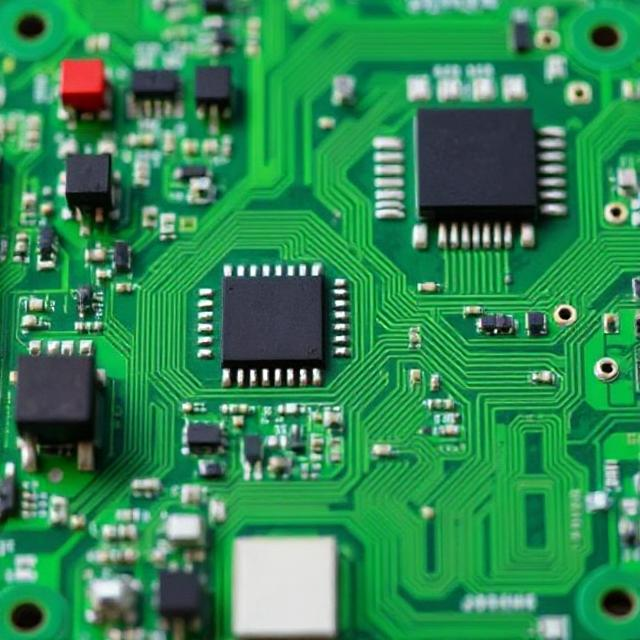
- Limited Size: Breadboards have limited space, so they’re not ideal for very large or complex circuits. If you need to make a more permanent and compact version of a circuit, you may need to use a PCB (Printed Circuit Board).
- Not for High-Voltage: Breadboards are generally used for low-voltage circuits. Using them with high voltage could be dangerous and may cause damage to the breadboard.
- Loose Connections: Sometimes, the connections on a breadboard may not be as secure as soldered connections. Components can become loose if the breadboard is moved.
6. How to Read a Breadboard:
- Rows and Columns: The breadboard usually has columns (vertical) and rows (horizontal). In the main part of the board, each row is connected with metal strips, which allows you to place components in the same row and they will be connected.
- Power Rails: The long rails on either side of the breadboard (usually marked “+” and “−”) are for connecting power to the circuit. They run the length of the breadboard and are not connected to the internal metal strips of the board.
7. Example: Building a Simple LED Circuit on a Breadboard
Here’s a simple example of how to set up an LED circuit:
- Insert the LED into the breadboard. The longer leg (anode) goes to the positive side, and the shorter leg (cathode) goes to the negative side.
- Connect a resistor to the anode (long leg) of the LED to limit the current.
- Use a jumper wire to connect the resistor’s other leg to the positive power rail.
- Connect the cathode of the LED to the negative power rail.
- Connect the power supply to the power rails. The positive terminal goes to the “+” rail, and the negative terminal goes to the “−” rail.
- Turn on the power, and the LED should light up!
Recap of Breadboards:
- What it is: A breadboard is a tool used for building and testing electronic circuits without soldering.
- How it works: You insert components into holes, and the metal strips inside the breadboard make connections between them.
- Benefits: Breadboards are quick, reusable, and perfect for prototyping and testing circuits.
- Limitations: They’re not ideal for high-voltage or large, complex circuits.


