What is AC (Alternating Current)?
Alternating Current (AC) is the type of current that changes direction periodically. In contrast to Direct Current (DC), which flows in one direction, AC’s direction switches back and forth.
The voltage in an AC circuit also alternates, rising and falling in a sinusoidal pattern. This is why you’ll often hear about sinusoidal waveforms in AC circuits.

What Does “Single-Phase” Mean?
Single-phase refers to a type of AC circuit that uses only one alternating current (or voltage) waveform. This is the simplest and most common form of AC power used in homes, small businesses, and some industries.
In single-phase AC, power is supplied through two wires: one for the live wire (which carries the current to the load) and one for the neutral wire (which carries the current back to the source).
In contrast, three-phase AC uses three separate alternating currents, but that’s a bit more advanced, so we’ll focus on single-phase here.
Key Concepts in Single-Phase AC Circuits
Voltage and Current Waveforms
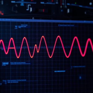
The voltage in an AC circuit follows a sinusoidal waveform, meaning it smoothly rises from zero, reaches a peak, falls back down, goes negative, and then rises again.
This is called a sine wave.
The frequency of the AC signal is measured in hertz (Hz), which tells us how many times the waveform repeats in one second. In most countries, the standard frequency for AC power is 50 Hz or 60 Hz.
-
Peak voltage is the highest voltage reached in the sine wave.
-
RMS (Root Mean Square) voltage is the effective voltage that performs the same work as a DC voltage. For example, a typical household outlet provides 120V RMS in the US.
Impedance (Z)
In AC circuits, impedance (Z) is the total opposition to current flow. Impedance is like resistance, but it also includes the effects of inductance (from coils) and capacitance (from capacitors).
Impedance is measured in ohms (Ω) and has both magnitude and phase, unlike resistance, which only affects the magnitude.
Ohm’s Law for AC Circuits
Ohm’s Law for AC circuits is similar to DC circuits but involves impedance (Z) instead of resistance (R):
Where:
-
V is the voltage across the load (in volts),
-
I is the current through the load (in amps),
-
Z is the impedance (in ohms).
In simple terms, this means the current in an AC circuit depends on the voltage applied and the impedance of the components.
Power in AC Circuits
The power in an AC circuit is the rate at which energy is consumed or supplied by the circuit.
-
Real Power (P): This is the actual power used by the circuit and is measured in watts (W). It’s the power that does work (like lighting a bulb).
-
Reactive Power (Q): This is the power that alternates between the source and the load without being consumed. It is measured in volt-amperes reactive (VAR).
-
Apparent Power (S): This is the total power (both real and reactive) supplied to the circuit, measured in volt-amperes (VA).
The relationship between these powers is shown by the power triangle:
Power Factor (PF)
The Power Factor (PF) is the ratio of real power to apparent power and is a measure of how efficiently the current is being used:
A power factor close to 1 means most of the power is being used effectively. A low power factor means a lot of energy is wasted.
Components of Single-Phase AC Circuits
-
Resistor (R):
A resistor in an AC circuit will only affect the magnitude of the current and voltage. It doesn’t cause a phase shift (the voltage and current are in sync with each other).
The current and voltage are in phase in a purely resistive circuit. -
Inductor (L):
An inductor resists changes in current. It causes the current to lag behind the voltage (the current peaks after the voltage peaks).
Inductive reactance (X_L) is the opposition to current due to inductance and is calculated as:Where:
-
is the frequency (in Hz),
-
is the inductance (in henries).
-
-
Capacitor (C):
A capacitor stores electrical energy in an electric field. It causes the current to lead the voltage (the current peaks before the voltage peaks).
Capacitive reactance (X_C) is the opposition to current due to capacitance and is calculated as:Where:
-
is the capacitance (in farads).
-
-
Combination of Resistor, Inductor, and Capacitor:
In a typical AC circuit, you may have a combination of resistors, inductors, and capacitors. The total impedance of the circuit is calculated by combining the individual resistances and reactances. For a series circuit:The impedance determines how much current will flow in the circuit.
Phasor Diagrams in Single-Phase AC Circuits
Phasor diagrams are graphical representations of the voltage and current waveforms in AC circuits.
In these diagrams, voltages and currents are represented as rotating vectors (phasors). The phasors rotate around a circle, showing how the voltage and current vary over time.
The angle between the voltage and current phasors indicates the phase difference between them:
-
In a purely resistive circuit, the voltage and current are in phase (no phase difference).
-
In an inductive circuit, the current lags the voltage.
-
In a capacitive circuit, the current leads the voltage.
Summary of Single-Phase AC Circuits
-
Single-phase AC circuits are circuits powered by an alternating current with a single waveform.
-
The current and voltage in these circuits change periodically, forming a sinusoidal wave.
-
Key elements include resistors, inductors, and capacitors, each affecting the current and voltage in different ways.
-
The relationship between voltage, current, and impedance is governed by Ohm’s Law for AC circuits.
-
Power is classified into real power (P), reactive power (Q), and apparent power (S), with power factor (PF) indicating how efficiently power is being used.
-
Phasor diagrams help visualize the phase relationships between current and voltage.
Why are Single-Phase AC Circuits Important?
Single-phase AC circuits are the most common form of electrical power used in homes and small businesses for powering everyday appliances like lights, fans, and refrigerators.


