What is a Circuit Diagram? Understanding Schematics
Introduction:
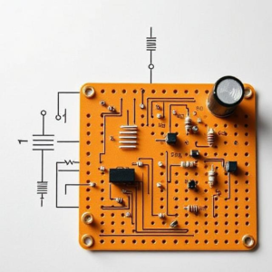
A circuit diagram, also known as a schematic diagram, is a visual representation of an electrical circuit. It uses symbols to represent electrical components and the connections between them. These diagrams are essential for engineers, electricians, and technicians to understand how a circuit is designed and how it functions.

In simple terms, a circuit diagram shows how different parts of a circuit are connected and how electrical current flows through them. It’s like a blueprint for building an electrical system.
Importance of Circuit Diagrams:
-
Clarity: A circuit diagram helps to clarify how each component of the circuit works and how they interact with each other.
-
Troubleshooting: If something goes wrong with a circuit, a diagram helps identify the problem and make repairs easier.
-
Planning: Before building a circuit, engineers use these diagrams to plan the design and ensure all components are connected properly.
-
Standardization: Circuit diagrams use universal symbols, making them easy to understand for anyone familiar with electrical systems.
Key Components in a Circuit Diagram:
-
Power Source: The power source (such as a battery or power supply) provides the energy needed to make the circuit work. In the diagram, a battery is represented by a pair of short and long lines (positive and negative terminals).
-
Resistors: A resistor limits the flow of electric current in the circuit. It is shown as a zigzag line in the diagram.
-
Capacitors: A capacitor stores and releases electrical energy. It is represented by two parallel lines with a gap between them.
-
Transistors: Transistors are used to amplify signals or act as a switch. In diagrams, they are represented by three lines that form a triangle or rectangle with three pins.
-
Switches: A switch controls the flow of electricity in a circuit, either allowing or stopping current. It’s shown by a break in a line with an additional symbol indicating on/off positions.
-
Wires and Connections: Wires are the conductors that carry the electrical current. In the diagram, they are represented as straight lines connecting the components.
Symbols Used in Circuit Diagrams:
Each electrical component is represented by a unique symbol in a circuit diagram. Some of the common symbols include:
-
Battery: Two lines (one longer, one shorter) connected.
-
Resistor: A zigzag line.
-
Capacitor: Two parallel lines with a gap in between.
-
Switch: A break in a line with a diagonal line indicating the switch action.
-
Wire: A straight line.
These symbols make it easy to read and interpret the function of each part of the circuit.
How to Read a Circuit Diagram:
Reading a circuit diagram involves understanding the layout of components and the paths through which electricity flows. Here’s how you can approach it:
-
Identify the power source: Look for the battery or power supply symbol. This is where the circuit gets its energy.
-
Trace the path: Follow the lines to see how current flows from the power source to different components like resistors, capacitors, and switches.
-
Check connections: Make sure the components are connected properly in the diagram. Broken or disconnected lines could indicate a malfunction or a design error.
Types of Circuit Diagrams:
-
Simple Circuit Diagrams: These diagrams represent basic circuits, usually involving a few components like a battery, resistor, and a light bulb. They are easy to understand and useful for beginners.
-
Complex Circuit Diagrams: These diagrams are used for more advanced circuits, like those found in industrial or electronic devices. They can contain many components and detailed connections, making them more difficult to read.
-
Block Diagrams: Sometimes, circuit diagrams are simplified into block diagrams, where complex components are represented as blocks. These are typically used for high-level understanding rather than detailed analysis.
Applications of Circuit Diagrams:
-
Home Appliances: Circuit diagrams are used in the design of everyday devices like refrigerators, fans, and air conditioners to ensure they work efficiently.
-
Electronics: All electronic gadgets, from mobile phones to computers, use circuit diagrams to lay out the internal components and ensure proper functioning.
-
Electrical Systems: Circuit diagrams are crucial in setting up electrical systems in buildings and factories, helping with everything from lighting to wiring in large machines.
Conclusion:
Circuit diagrams, or schematics, are vital tools for understanding and building electrical circuits. They provide a clear and organized way to represent electrical systems and are used by professionals to design, troubleshoot, and repair circuits. By understanding the symbols and layout of circuit diagrams, anyone can learn how electrical devices work and how to safely interact with electrical systems. Whether you are a beginner or an experienced technician, learning to read circuit diagrams is an essential skill in the world of electronics and electrical engineering.


